Chapter 5: oscillators and filters 118 a, A6 r, Notch the – ALESIS ANDROMEDA A6 User Manual
Page 120: As the input to, Turning the
Chapter 5: Oscillators and Filters
118
A
NDROMEDA
A6 R
EFERENCE
M
ANUAL
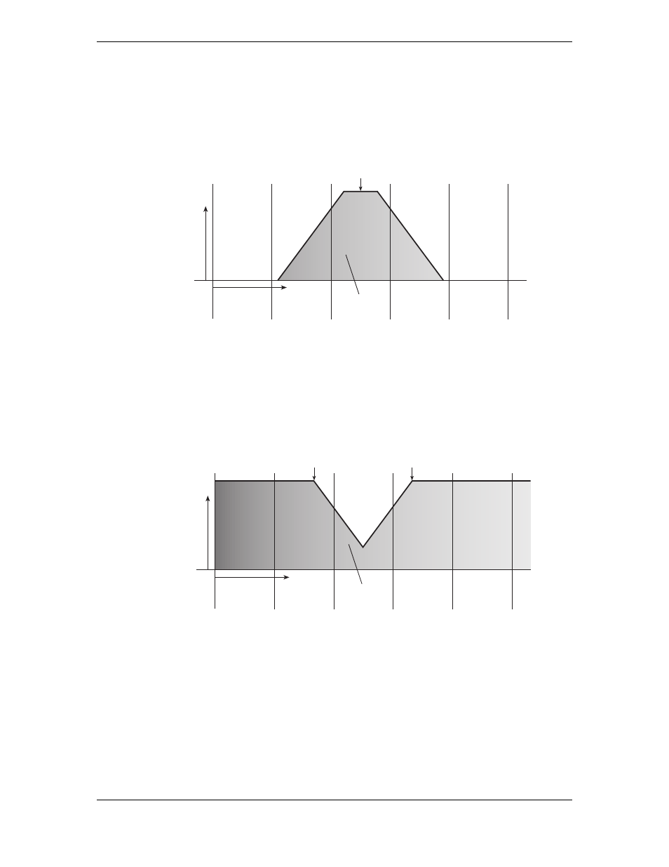
Band Pass
A section of the audio spectrum, called a “band of frequencies”, passes through the
filter while low and high frequencies are filtered out. Turning the
FREQ
knob
determines the center frequency of the band: harmonics just above and below this
center frequency make up the band; harmonics to the extreme above and below are
filtered out.
1 kHz
2 kHz
5 kHz
10 kHz
20 kHz
FREQUENCY
AMPLITUDE
HARMONIC
SPECTRUM
CENTER
FREQUENCY
Notch
The
FILTER 1
’s notch filter is not a specific hardware filter like low, high or band pass
filtering. Rather, notch filtering is created by combining the filtering characteristics of
the low pass filter and the high pass filter. The notch of Filter 1 is pre-set by the A6,
and is very narrow:
1 kHz
2 kHz
5 kHz
10 kHz
20 kHz
FREQUENCY
AMPLITUDE
HARMONIC
SPECTRUM
HIGH PASS
CUTOFF
FREQUENCY
LOW PASS
CUTOFF
FREQUENCY
The opposite of band pass , notch filtering is sometimes referred to as “band-reject”
filtering because it filters out a band of frequencies rather than passing them through.
The A6 goes one further by actually providing true band-reject filtering by
permitting you to invert the band pass filter, as covered in the next topic.
There is a way in the A6 to create a notch that has a variable width and depth. By
selecting
MIX
as the input to
FILTER 2
, turning the
FILT1 LP
knob off (fully counter-
clockwise) and turning the
FILT1 HP
knob up (fully clockwise), you are effectively
running
FILTER 1
and
FILTER 2
in parallel, with Filter 1 passing the high end and Filter
2 passing the low end.