Lcd display transistor illustration – Aiwa CSD-TD53 User Manual
Page 7
8
7
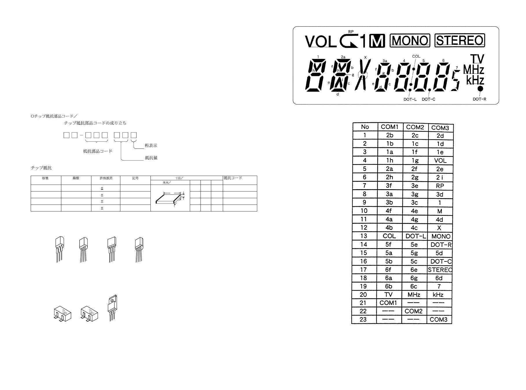
LCD DISPLAY
TRANSISTOR ILLUSTRATION
•
Regarding connectors, they are not stocked as they are not the initial order items.
The connectors are available after they are supplied from connector manufacturers upon the order is received.
8 8
A
Resistor Code
Chip Resistor Part Coding
Figure
Value of resistor
Chip resistor
Wattage
Type
Tolerance
1/16W
1/10W
1/8W
1608
2125
3216
5%
5%
5%
CJ
CJ
CJ
Form
L
W
t
1.6
0.8
0.45
2
1.25
0.45
3.2
1.6
108
118
128
: A
: A
CHIP RESISTOR PART CODE
0.55
Resistor Code
Dimensions (mm)
Symbol
1/16W
1005
5%
CJ
1.0
0.5
0.35
104
L
t
W
MOTOR C.B
M2 9X-262-576-910 MOTOR GEAR ASSY
PIN3 91-564-722-110 CONNECTOR 6P
SW1 91-572-085-120 LEAF SW
KEY C.B
S608 87-A91-704-080 SW,TACT EVQ 214 05R
S609 87-A90-164-080 SW,TACT SKQAB(N)
S610 87-A90-164-080 SW,TACT SKQAB(N)
REF. NO
PART NO.
KANRI
DESCRIPTION
NO.
E
B
C
E C B
E C B
E C B
E C B
B C E
2SA1162
2SC2712
2SC2714
DTA114YK
DTC114TK
DTC114YK
DTC124XK
DTC144TK
G
D
S
2SK302
2SA1296
2SC1815
2SC2001
2SA933
2SC1740
DTC114TS
DTC124XS
2SA1318
2SB1370