Disassembly procedure flowchart – Acer 330 User Manual
Page 65
Chapter 3
65
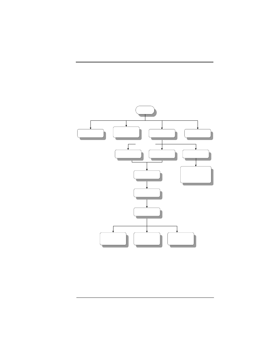
Disassembly Procedure Flowchart
The flowchart on the succeeding page gives you a graphic representation on
the entire disassembly sequence and instructs you on the components that
need to be removed during servicing. For example, if you want to remove the
system board, you must first remove the keyboard, then disassemble the
inside assembly frame in that order
START
8 6.9 A32 2 .4 R 0 *2
sc re w M 2 .0 *4
H D D M o d u le
In ve rte r/L E D
C a b le
In ve rte r/L E D
B o a rd
L C D C o a xia l
C a b le
L C D a n d
In ve rte r b o a rd
L C D B e z e l
L C D M o d u le
M ain Unit
(se e n e xt p a g e )
L C D C o a xia l
C a b le
In ve rte r C a b le
K e yb o a rd
B a tte ry
M id d le C o ve r
E xte n d D IM M
C o ve r
8 6 .9 A3 22 .9R 0 *1
sc re w M 2 .0*9
8 6.9 A32 2 .4 R 0 *2
sc re w M 2 .0 *4
8 6.9 A32 2 .4 R 0*2
sc re w M 2 .0*4
8 6 .9 A3 53 .6R 0 *2
s cre w M 2.5 *6
8 6 .9 A3 23 .4R 0 *4
s cre w M 2.5 *4
8 6 .9 A3 23 .4R 0 *6
s cre w M 2.5 *4
- Aspire 5741ZG (2345 pages)
- Aspire 5741ZG (313 pages)
- TravelMate 5330 (14 pages)
- Extensa 7230 (86 pages)
- AOD257 (1810 pages)
- AO753 (374 pages)
- AO533 (4 pages)
- AOD255 (299 pages)
- AO522 (1810 pages)
- Aspire V5-531G (2484 pages)
- Aspire EC-471G (10 pages)
- Aspire M3-581PTG (10 pages)
- Aspire M3-581TG (3478 pages)
- Aspire M3-581TG (11 pages)
- Aspire 8950G (378 pages)
- Aspire EC-471G (11 pages)
- Aspire V5-571PG (3604 pages)
- Aspire E1-571 (308 pages)
- Aspire E1-521 (11 pages)
- Aspire S5-391 (111 pages)
- Aspire S5-391 (11 pages)
- Aspire M5-581TG (10 pages)
- Aspire M5-581TG (11 pages)
- Aspire V3-471G (362 pages)
- Aspire V3-471G (11 pages)
- Aspire M5-481TG (11 pages)
- Aspire 9420 (109 pages)
- Aspire 9520 (123 pages)
- 3280 (106 pages)
- 4600 (128 pages)
- Aspire 1300 (96 pages)
- 4330 (198 pages)
- TravelMate 3250 (98 pages)
- 1450 (99 pages)
- 2420 (108 pages)
- 310 (2 pages)
- 310 (130 pages)
- 3690 (123 pages)
- 5010 (113 pages)
- 3250 (124 pages)
- 5560 (112 pages)
- 5230 (176 pages)
- 420 series (78 pages)
- 3000 (109 pages)
- 3200 Series (90 pages)