Names mounting, Jf-dv unit, Position of mounting bracket 4. installation – Aiphone AC-10F User Manual
Page 4: Positions for drilling holes
3
English
Nederlands
Français
Deutsch
Español
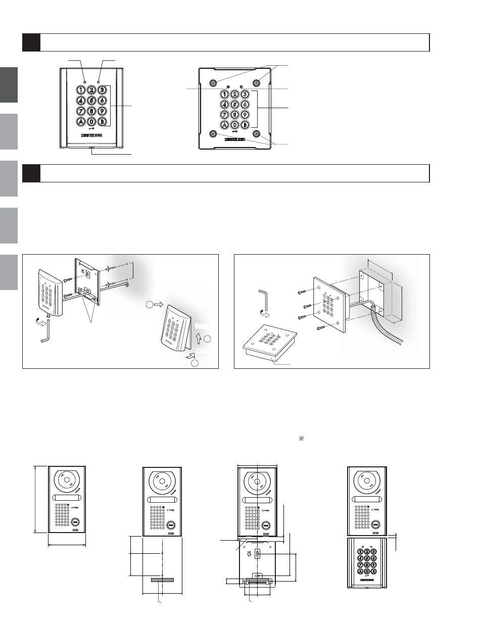
NAMES
MOUNTING
1
2
4
3
AC-10S
1. Drill holes in the wall to match the size and number of screws.
2. Attach the mounting bracket to the wall using the
mounting screws.
3. Attach the unit to the mounting bracket using the special
screwdriver and the special screw for mounting.
When this unit is to be used with the JF-DV, please refer to the illustration below when installing it.
Please also refer to "TEMPLATE FOR AC-10S MOUNTING BRACKET(SCALE 1:1)"(page 42).
Attach the unit to the mounting bracket
by pushing it into the bracket. Tighten
the screws to complete the installation.
( ) As there are drain holes at the bottom
of the JF-DV unit, do not block the space
between the JF-DV and the access control
keypad.
1 LED indicator (Orange)
2 LED indicator (Green)
3 Keys (Yellow)
4 Special screws for panel mounting
1. JF-DV unit
Refer to the illustration
below when attaching the
mounting bracket.
3. Position of mounting bracket
4. Installation
AC-10F
1. Detach the AC-10F panel using the special screwdriver
supplied.
2. Attach the flush mount back box to the wall.
3. Attach the panel to the flush mount back box using the special
screwdriver and the special screws for panel mounting.
Please refer to the
illustration below when
drilling the holes. Make
sure the cable inlet is within
the shaded area shown in
the illustration below.
2. Positions for drilling holes
Spare screw holes
Cable
Wall
Wall
Click
55mm (2-3/16")
45mm
(1-12/16")
Flush mount back box
100mm
(3-15/16")
85mm (3-3/8")
5mm (3/16")
98mm (3-7/8")
173mm (6-13/16")
98mm (3-7/8")
1
1
.5mm (7/16")
3.5mm
(1/8")
49mm (1-15/16")
42.5mm
(1-2/3")
55mm
(2-3/16")
68.5mm (2-1
1/16")
Cable inlet
64mm (2-1/2")
15mm (9/16")
49mm
(1-15/16")
49mm
(1-15/16")
42.5mm
(1-2/3")
55mm
(2-3/16")
A hole for cable inlet