Wiring, 1 ttm-p4 series, 3 caution on wiring – TOHO ELECTRONICS TTM-P9 User Manual
Page 4: 2 ttm-p9 series
3
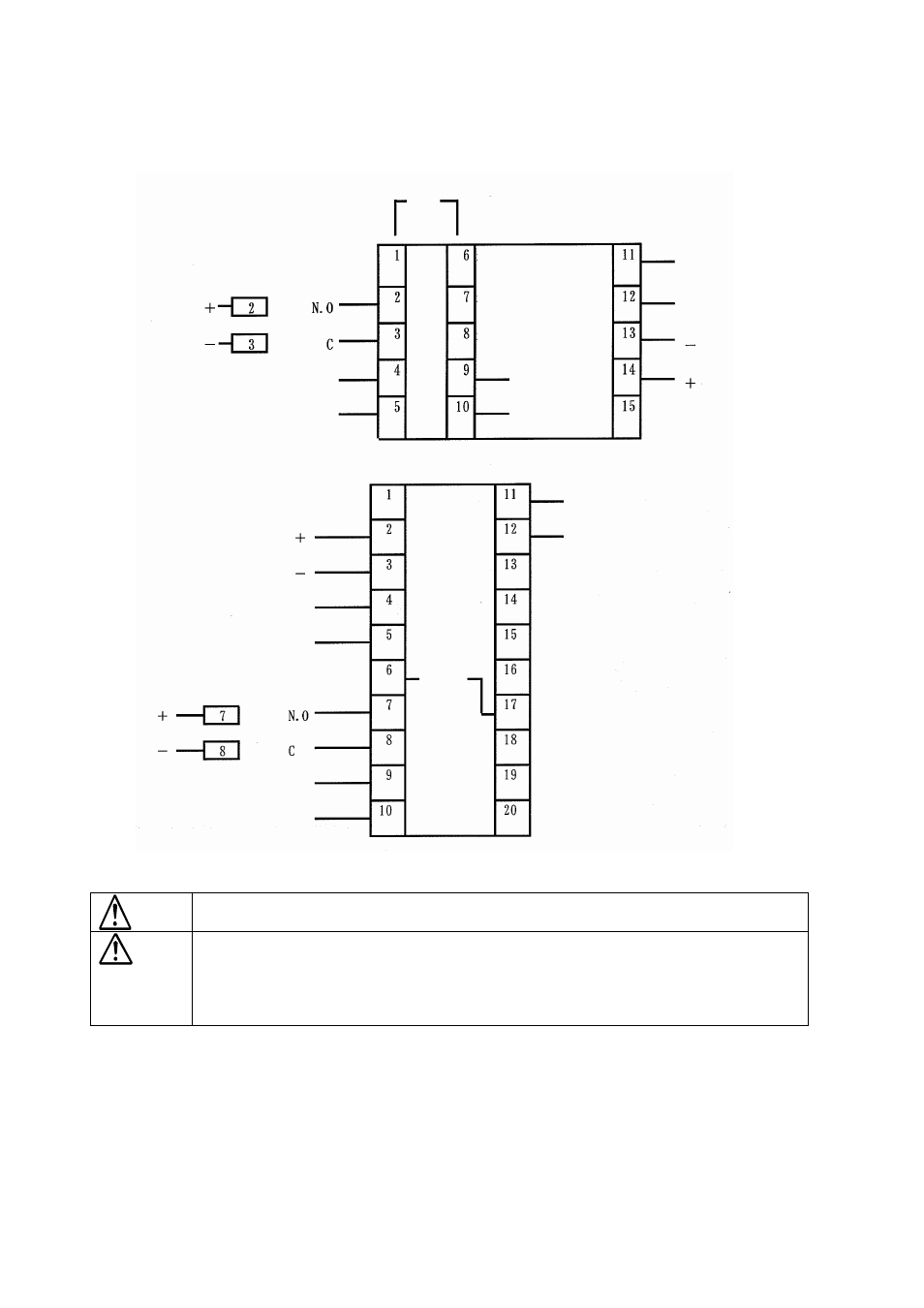
3. Wiring
3.1 TTM-P4 series
SSR drive
Control output
Power supply voltage
100 to 240VAC
±
10%
Relay contact
Operation signal
Output
Reserved
Reserved
Reserved
DI
(external input)
Time signal output/
alarm
Thermocouple input (K/J/R)
Reserved
Reserved
Reserved
Reserved
Reserved
Reserved
Reserved
Reserved
Reserved
DI
(external input)
Operation
signal
Output
SSR drive
Control output
Power supply voltage
100 to 240VAC
±
10%
Relay contact
Time signal output/alarm
Thermocouple input (K/J/R)
3.3 Caution on wiring
Before wiring, be sure to turn off the power supply. Otherwise, you may get an electric
shock.
This equipment does not execute control operation for about 4 seconds after the power is
turned on. (Control output does not work. during the period)
Pay attention when you use this equipment for interlock circuit.
Confirm the wirings of the input terminal, power terminal, and optional terminal by reading
the label at the side of the equipment.
- Use crimping terminals matching to M3.5 screws. Also, when you wire to the central terminals, tighten the wire
directly.
- As for wire rods to be used for connecting this equipment with a thermocouple, use a specific compensating lead
wire or wire itself.
- When you use this equipment near the source of noise, use a shielded wire. Also, do not wire the input/output line
in the same duct or wire conduit.
- Leave the input/output signal line more than 50 cm away from the power and load lines.
3.2 TTM-P9 series
Warning
Caution