Connections – TOHO ELECTRONICS TTM000 User Manual
Page 36
36
8. Connections
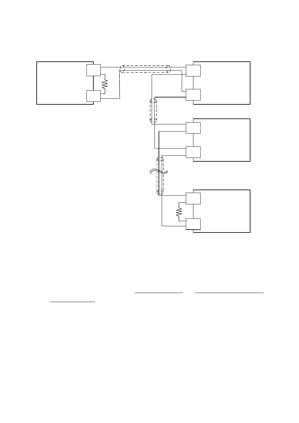
Host Computer
(Master Station)
Unit1
(Slave Station)
Unit2
(Slave Station)
Unit3
(Slave Station)
A(+)
B(-)
A(+)
B(-)
A(+)
B(-)
A(+)
B(-)
terminating
resistor
①
terminatin
g resistor
②
Cable①
Cable②
Cable③
○
Above drawing shows example of connecting 1 to 3 slave stations to a master station.
◇
Use cables with the same characteristic impedance for cables ① to ③.
- For slave station nos. 1 to 3, connect them dependently as shown in the drawing.
The same characteristic impedance cables are used for the connections between
the slave stations.
◇
Attach terminating resistor to both the master station side ① and the farthest ② ones among the
slave stations (no. 3).
◇
Make sure to select terminating resistor in order that the [Characteristic Impedance from cables ①
to ③] = [Resistance Value of ①] = [Resistance Value of ②]
- Furthermore, use characteristic impedance cable whose [Resistance Value of ①] // [Resistance
Value of ②] (parallel combination resistance value) becomes above 75-ohms.