Water connections, Pressure relief valve – State GTS-110-NI User Manual
Page 20
Installation
20
│
Page
Do not use this water heater if any part has been submersed under water.
Immediately call a licensed professional to inspect the water heater to replace
any damaged parts.
Do not reverse the hot outlet and cold inlet connections to the water heater.
This will not properly activate the water heater.
WATER CONNECTIONS
All pipes, pipe fittings, valves and other components, including soldering materials, must be suitable for
potable water systems.
1.
A manual shut off valve must be installed on the cold water inlet to the water heater between
the main water supply line and the water heater.
2.
In addition, a manual shut off valve is also
recommended on the hot water outlet of the
unit. If the water heater is installed within, or
subjected to, a closed loop water system, a
thermal expansion tank must be installed.
3.
Before installing the water heater, flush the
water line to remove all debris, and after
installation is complete, purge the air from the
line. Failure to do so may cause damage to the
heater.
4.
There is a wire mesh filter within the cold inlet
to trap debris from entering your heater. This
will need to be cleaned periodically to maintain
optimum flow.
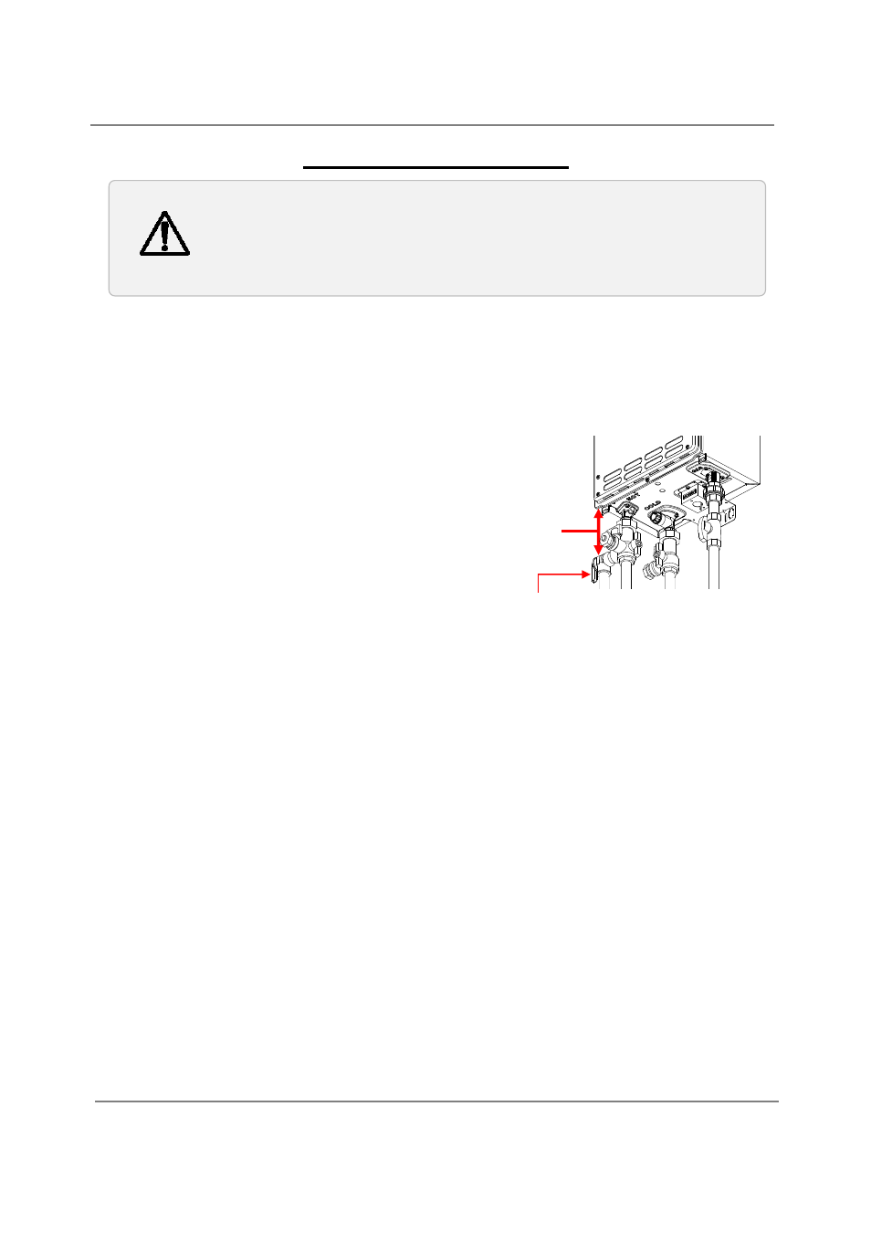
‐Pressure relief valve‐
The water heater has a high‐temperature shut off switch built in as a standard safety feature (called a
Hi‐Limit switch) therefore a “pressure only” relief valve is required.
This unit does not come with an approved pressure relief valve.
An approved pressure relief valve must be installed on the hot water outlet.
The pressure relief valve must conform to ANSI Z21.22 or CAN 1‐4.4 and installation must follow
local code.
The discharge capacity must be at least 140,000 BTU/h for the 110 (T‐KJr2) models, 190,000
BTU/h for the 310 (T‐K4) models, and 199,000 BTU/h for the 510 (T‐D2) models.
The pressure relief valve needs to be rated for a maximum of 150 psi.
The discharge piping for the pressure relief valve must be directed so that the hot water cannot
splash on anyone or on nearby equipment.
Attach the discharge tube to the pressure relief valve and run the end of the tube to within 6"
from the floor. This discharge tube must allow free and complete drainage without any
restrictions.
If the pressure relief valve installed on the water heater discharges periodically, this may be due
to a defective thermal expansion tank or defective pressure relief valve.
The pressure relief valve must be manually operated periodically to check for correct operation.
No valve must be placed between the relief valve and the water heater.
Pressure
Relief Valve
Hot
outlet
Cold
inlet
Gas
inlet
As Close as
Possible
CAUTION