Installation – State GTS-110-NI User Manual
Page 13
Installation
13
│
Page
‐Exhaust venting‐
For the 110 Indoor (T‐KJr2‐IN), 310 Indoor (T‐K4‐IN) and 510 Indoor
(T‐D2‐IN) models
This is a Category III appliance and must be vented accordingly. The vent system must be sealed air tight.
All seams and joints without gaskets must be sealed with high heat resistant silicone sealant or UL listed
aluminum adhesive tape having a minimum temperature rating of 350°F. For best results, a vent system
should be as short and straight as possible.
This water heater is a Category III appliance and must be vented accordingly with any 4” vent
approved for use with Category III or Special BH type gas vent.
Follow the vent pipe manufacturer’s instructions when installing the vent pipe.
Do not common vent this appliance with any other vented appliance (Do not terminate vent
into a chimney. If the vent must go through the chimney, the vent must run all the way
through the chimney with Category III approved or Special BH vent pipe).
When the horizontal vent run exceeds 5 ft., support the vent run at 3 ft. intervals with
overhead hangars.
The maximum length of exhaust vent piping must not exceed 50 ft. (deducting 5 ft. for each
elbow used in the venting system). Do not use more than 5 elbows.
Diameter
Max. No. of Elbow
Max. Vertical and Horizontal (Total) Vent Length
4”
5
50 ft.
*For each elbow added, deduct 5 ft. from max. Vent length.
No. of Elbows
Max. Vertical or Horizontal Length
0
50 ft.
1
45 ft.
2
40 ft.
5
25 ft.
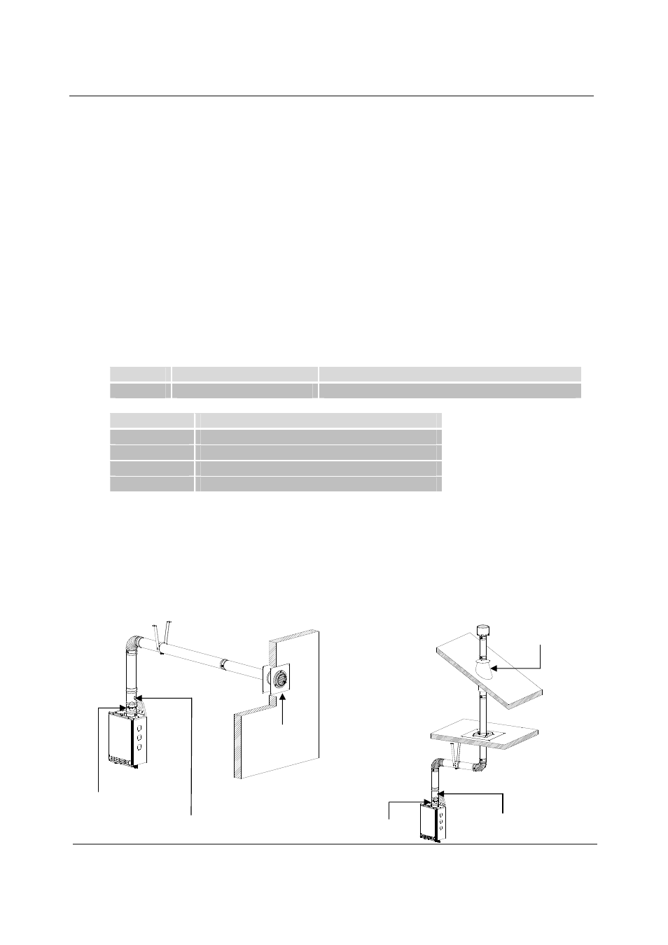
‐Venting Illustrations‐
For the 110 Indoor (T‐KJr2‐IN), 310 Indoor (T‐K4‐IN) and 510 Indoor
(T‐D2‐IN) models
Horizontal Installation Diagram
Vertical Installation Diagram
Sidewall Vent
Terminator
Wall
Backflow Preventer*
Vertical Condensation Drain**
For details of the optional items, refer to the Installation manual for each Optional item.
Roof
Vertical Condensation
Drain**
Roof Flashing
Rain Cap
Backflow Preventer *