Warning – Sterlco 2016C (Former Compact Series) User Manual
Page 44
Page 44
2016-C Series Hot Oil Portable Temperature Control Units
Thrust Bearing Adjustment
1. Loosen axial setscrews in face of end cap on the thrust bearing
assembly. If rotor shaft cannot be turned by hand, back off the
thrust bearing assembly until there is a noticeable drag of the
shaft. Note mechanical seal will provide some drag and this is
a normal condition. The thrust bearing assembly must be
turned in until it can just be turned over by hand. This ensures
the rotor is against the head and a zero end clearance condition
exists.
2. Make a mark on the OD of the bearing housing and a
corresponding mark on the bracket. Back off thrust bearing
housing the required number of marks or distance on the OD
as shown below.
3. Tighten the axial setscrews in the face of the thrust bearing
assembly. Make sure the rotor shaft turns freely. If it does
not, repeat steps 1 and 2.
*Each small notch on outer end cap represents .001 inch end clearance.
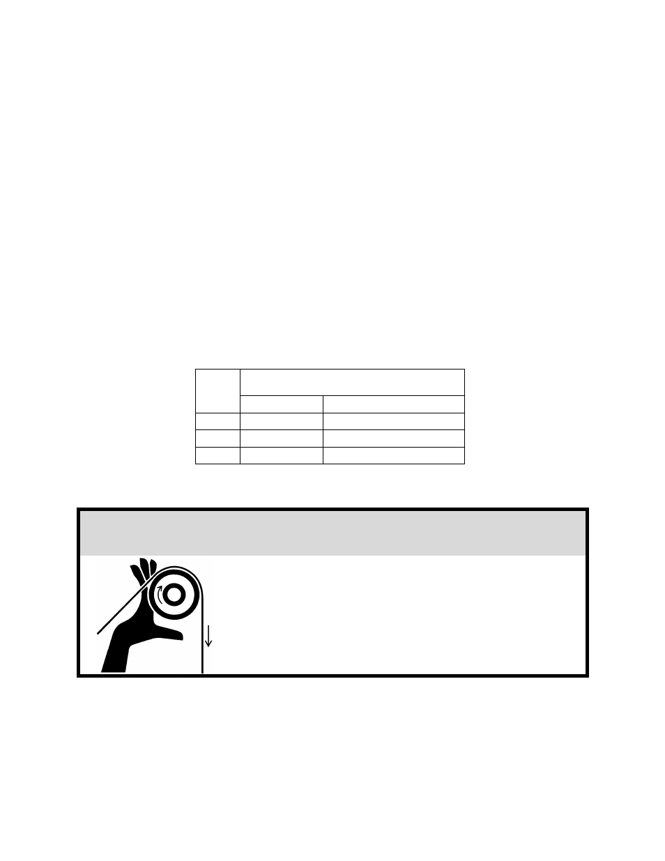
!
WARNING
Before starting the pump, make sure that all
drive equipment guards are in place!
Failure to properly install the guards may result
in serious injury or death!
PUMP
SIZE
Turn Outer End Cap C.C.W.
No. of Notches*
or Length on O.D., Inches
G
-
0.75"
HL, HV
6
1"
KK
10
1.38"