Setra System Model 231RS User Manual
Page 9
9
3.0 ELECTRICAL INSTALLATION
To access the electrical connections, turn the screws on the top of the case counter clockwise until the hinged cover
can be flipped up. The screws are captured and secured in the cover. Wiring is through the 1/2” conduit openings
and PG fittings in the case of remote sensors with cable option. Both current and voltage outputs are reverse wiring
protected.
Note: The Zero terminals, connected to digital output, provide a contact closure relay for automatic reset to zero pres-
sure by the monitoring system. CAUTION: ZERO input is for dry contact, do no apply voltage to ZERO Terminals
3.1 Electrical Termination
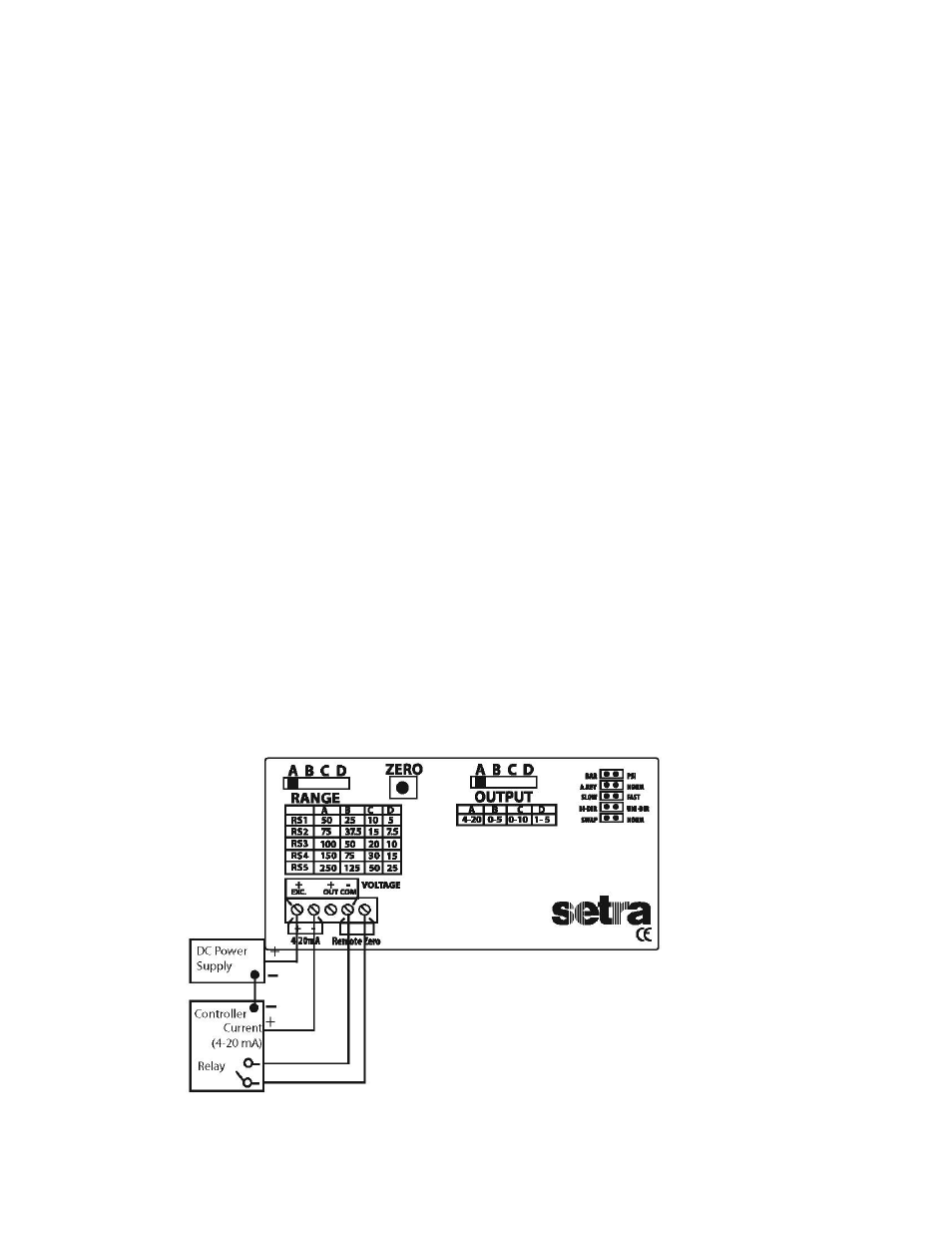
Wiring: 2-Wire - 4 to 20 mA (Current Output) and Remote Zero
Model 231RS when configured as a current output transducer is a true 2-wire, 4-20 mA current output device and
delivers rated current into any external load of 0-250 ohms.
When configured as a 4-20 mA current output device the current flow is in one direction only.
PLEASE OBSERVE POLARITY. WARNING: Damage may result on the unit if AC power is applied when the output
switch is configured in position “A” (4-20).
We suggest that an electrical cable shield be connected to the system’s loop circuit ground to improve electrical noise
isolation.
Min. Supply Voltage: 15 + .02 x (Resistance of receiver plus line)
Max. Supply Voltage: 30 + .004 x (Resistance of receiver plus line)
The optional remote zero is a normally open relay wired between COM and REMOTE ZERO terminals. In order to initi-
ate ZERO function the relay contact should be closed and sensor must be vented to atmosphere.
Figure 4