Figure b terminal block connector – Setra System Model Datum 2000 User Manual
Page 6
6
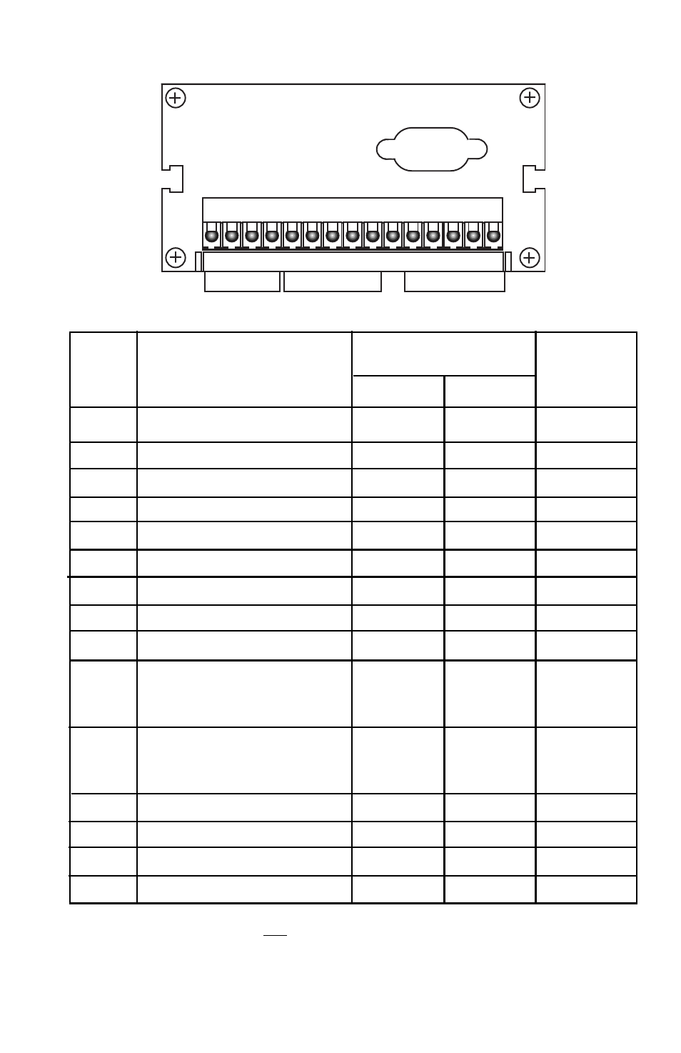
1 2 3 4 5 6 7 8 9 10 111213 14 15
Channel 1
Inputs/Excitations
Channel 2
Inputs/Excitations
Alarm
Signals
Figure B
Terminal Block Connector
Setra
Setra
Transducer*
Transmitter*
Pin
Description
w/Red
Cable w/Gray
Cable w/Gray
Cable
1
.
Ground
2
.
Hi
ALArm
3
.
Lo
ALArm
4
.
Ch.
1
/
Ch.
2
5
.
+24
Volts
excitation
White
Red
Red
6
.
Ch.
1
+
In
Yellow
Green
7
.
Ch.
1
-In
Brown
White
8
.
Ch.
1
Current
input
Black
9
.
Ground
Black/Shield
Black/Shield
Shield
10.
+
12
Volts
excitation
(optional)
White
Red
Caution:
Do
not
common
to
Pin
5
or
Pin
11
(+24V
exc.)
11.
+
24
Volts
excitation
White
Red
Red
Caution:
Do
not
common
to
Pin
10
(+12V
exc.)
12..
Ch.
2
+
In
Yellow
Green
13.
Ch.
2
-
In
Brown
White
14.
Ch.
2
Current
input
Black
15.
Ground
Black/Shield
Black/Shield
Shield
*IMPORTANT:
If you are not using a Setra transducer or transmitter, see
manufacturer's transducer/transmitter operating instructions for terminal
circuit configuration and then connect the wires to the corresponding pins
listed in the above chart.