2 calibration adjustment – Setra System Model 595 User Manual
Page 7
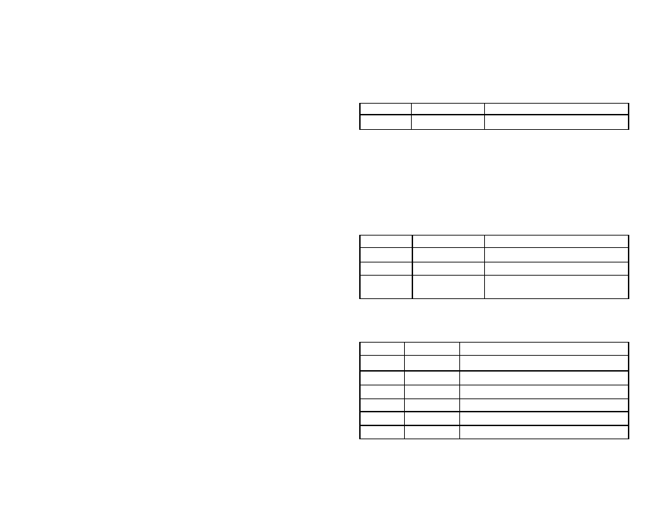
The temperature is a measured value and thus the density of water at any given
time is calculated by the transducer. The user may enter a local gravity value via
the XE command as detailed in Table 4
Table 4
Entering the Local Gravity
Command
Response
Comment
aXE9.81!
a9.81
Sets the local gravity value to 9.81 m/s
2
7.2.3 Selecting a Commonly Used Unit of Measurement
For SDI12 output units it is possible to change the units of the measured vari-
ables, pressure and temperature. The extended commands aXUTn! and aXUPn!
are used to change the temperature and pressure units respectively. Note the
value of n specifies the required unit as shown in Tables 5 and 6.
Table 5
Selecting Temperature Units
Command
Response
Comment
aXUT0!
a0
Sets the temperature units to
°C
aXUT1!
a1
Sets the temperature units to
°F
aXUT!
a1
Queries the temperature unit without
setting a value
Table 6
Selecting Pressure Units
Command
Response
Comment
aXUP0!
a0
Sets the pressure units to mH
2
O
aXUP1!
a1
Sets the pressure units to ftH
2
O
aXUP2!
a2
Sets the pressure units to inH
2
O
aXUP3!
a3
Sets the pressure units to bar
aXUP4!
a4
Sets the pressure units to psi
aXUP!
a4
Queries the pressure unit without setting a value
Note: The pressure units (bar, psi) are not valid when configured for a true level output
8.2 Calibration Adjustment
The 595 is designed to provide excellent long-term stability, however, occasion-
ally it is necessary to verify the calibration and perform adjustment. Setra offers an
annual recalibration service, via return to the service department. Alternatively a
two point calibration adjustment of each variable provided by the 595 is possible
via the SDI12 interface. This is achieved through three independent adjustments
i.e. pressure, temperature and mA output. The recommended calibration proce-
dure is detailed in Figure 1. Writing of calibration adjustment values is performed
via the aXZ and aXG commands. These commands have the following syntax:
aXZn,
aXGn,
where:
n = channel to be calibrated
Three calibration channels are supported:
n = 0 = Pressure
n = 1 = Temperature
n = 2 = mA Output (response to pressure signal)
n = 3 = mA Output (fixed output)
Calibration of any channel is basically the same and consists of 9 simple steps:
1. Apply zero scale value and record the measured value.
2. Apply full scale value and record the measured value.
3. Calculate the errors and adjustment values (if required.)
4. Write the calibration adjustment values to the 595.
5. Apply zero scale values and record the measured value.
6 Apply full scale value and record the measured value.
7. Calculate new errors and record results.
8. Write the last and next calibration dates.
9. Save the calibration.
8.2.1 Example of mA Output Calibration
T
he mA Output consists of two discrete components:
1. The analogue to digital conversion of the measured pressure and temperature
values.
2. The digital to analogue conversion, providing the analogue output.
Step 1 in Figure 1 refers to checking the calibration of the digital to analogue
conversion of the mA output. For SDI12 output, this step is not necessary. The
calibration of mA output stage can be verified using an extended command to
set a fixed mA output value as shown in Table 12