2 electrical installation – Setra System Model 595 User Manual
Page 5
6.2 Electrical Installation
The 595 requires a D.C. power supply between 8V and 30V. The 595 includes
suppression devices providing surge protection. In the event of a surge these
devices can clamp across the power supply, providing protection against the
surge. To avoid damage to the protection devices the power supply must be
current limited so that the maximum normal operating current is 100mA. Where
batteries are used directly this can easily be achieved via a series resistor, of
suitable nominal value and power rating. For mA output units, the second
consideration is the total resistance in the current loop. The maximum loop
resistance is calculated by the formula:
Maximum Loop Resistance = (Vx - 8) * 50 ohms
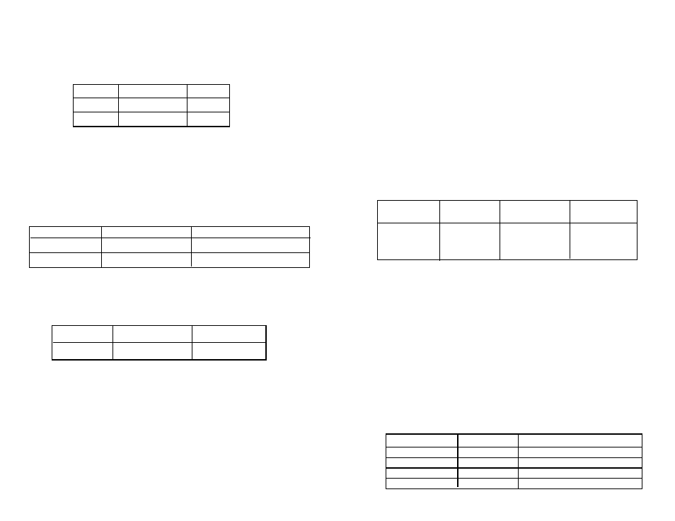
Table 1 states the minimum and maximum resistance recommended.
Table 1
Recommended Power Supply Current Limit
Power Supply
Current Limit
Series Resistance Maximum Loop
Voltage
Limit
Note 1
Resistance
12
0.1A
120 ohm
200 ohm
24
0.1A
240 ohm
800 ohm
30
0.1A
300 ohm
1100 ohm
Note 1.: Minimum series resistance only required where current limit of 0.1A is not
provided by power supply.
The cable comprises 4 color-coded cores, with a central vent tube, enclosed by an
aluminum/polyester screen where the screen is in intimate contact with a
separate drain wire. The outer sheath can be of various material, depending upon
application and operating temperature, standard suitable for most water environ-
ments is Polyurethane (immersed operating temperature -20
°C to +50°C). Other
cables are available on request for operation at higher temperatures or in more
corrosive media. The cable should be terminated in a dry environment to avoid
moisture entering the vent tube. If water enters this tube then erroneous
measurements may result. In humid environments then it is recommended to
terminate the cable into a suitable desiccator (see Setra’s Model 299). The
following electrical connections should be made:
Table 2
Connections mA Output Probes
Wire Color
Signal Name
Description
Red
VEx_+ve
Positive Excitation for the Probe
Blue
Vex_-ve
Negative Excitation for the Probe
None/Screen
Ground
Metalwork of Probe
Green*
SDI12
SDI12 Data
* Not required for 4 to 20 mA output operation
Step 6: Apply Full Scale Value
Set Point Value 20 mA, actual reading 19.999 mA
Step 7: Calculate Errors and Record Results
Applied
Measured
Error
4.000
4.001
0.001
20.000
19.999
-0.001
Step 8 Write the Calibration Dates
Calibration dates are stored as nine character ASCII string. Assuming the
calibration date was March 3rd 2005, then the dates could be written as
shown in Table 14.
Table 14
Writing the Calibration Dates
Command
Response
Comment
aXL,03MAR2005!
a03MAR2005
Writes the last calibration date.
aXN,03MAR2006!
a03MAR2006
Writes the next calibration date.
Step 9 Save the Calibration
All data written remains nonvolatile until the save command is executed
as shown in Table 15.
Command
Response
Comment
AXS0!
a0!
Saves all data