0 operation, 1 analogue output probes, 2 sdi12 operation – Setra System Model 595 User Manual
Page 6
It is recommended to firmly secure the Kevlar core of the cable, for example, by
knotting and securing under a fixing screw.
7.0 Operation
Having installed the transducer as instructed it is ready for use. Before applying
power, check that the correct polarity and excitation levels are being applied. See
Electrical Installation (6.2).
7.1 Analogue Output Probes
Analogue output devices will simply provide a 4 mA output for 0 level and a 20
mA output for the full scale level indicated on the product label. The analogue
output can be adjusted via the digital SDI12 interface with a suitable accessory to
include site offsets or provide full scale, 20 mA, output at a different level.
7.2 SDI12 Operation
The SDI12 interface conforms with the SDI12 V1.3 specification. Refer to the SDI12
host web-site for a full specification, http://www.sdi-12.org.
In addition to the standard SDI12 command set, the 595 supports a number of
extended commands, providing increased levels of functionality. All sample
commands provided are shown with address “a” , to use the command substitute
the actual address of the unit. The default address when manufactured is “0”.
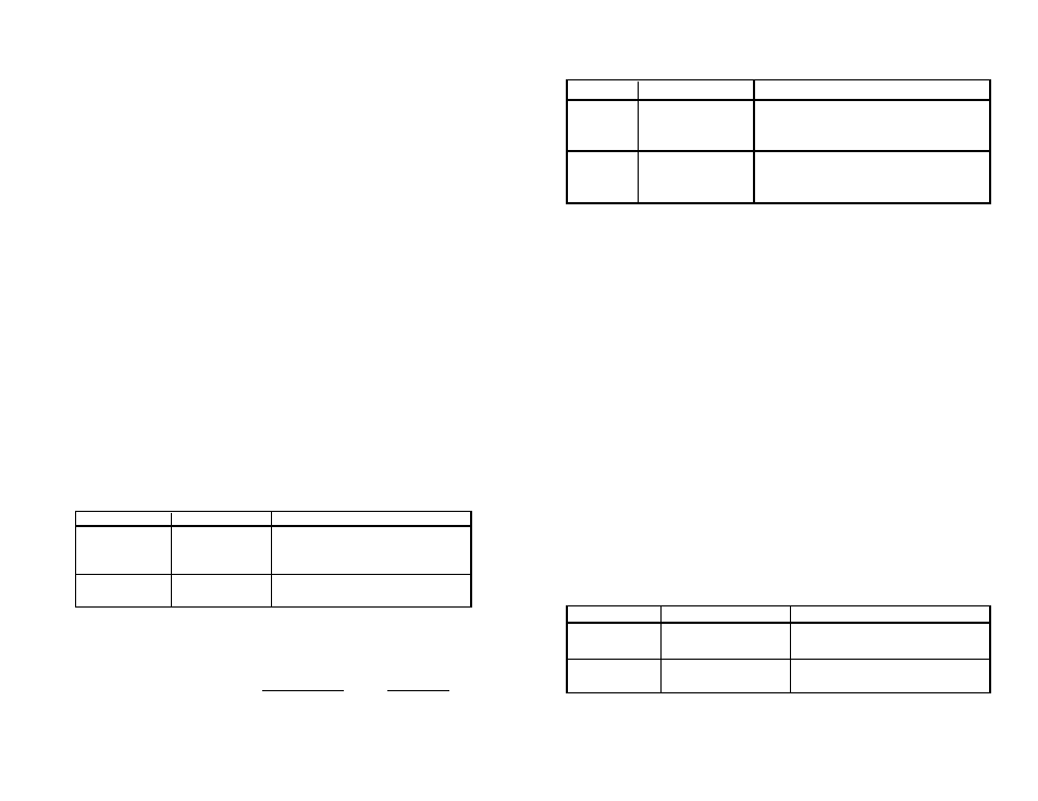
7.2.1 Setting up the Measured Variable
The transducer can provide either an output proportional to the applied pressure
or a true level compensated for relative density of water. The preferred measured
value must be set by the XP command as detailed in Table 3.
Table 3
Setting the Measured Variable
Command
Response
Comment
aXP0!
a0
Set true level measure, compen-
sated for relative density of water
over temperature and local gravity.
aXP1!
a1
Set pressure measure, no additional
compensation.
7.2.2 Making a Level Measurement
The corrected level measurement is calculated in the following manner.
Level = mH
2
O pressure at 4
°C
*
1
*
9.80665
density of water
local gravity
where:
Density of water = -6.017777e-6t
2
= 0.0000408t+0.999841
where t - temperature in
°C.
Table 12
Calibration of the mA Output
Command
Response
Comment
aXM4
a4.00000
Measure the current and record the actual
value.
aXM20
a20.0000
Measure the current and record the actual
value.
Step 1:
Apply Zero Scale Value
Set Point Value 4mA, actual reading 4.005 mA.
Step 2:
Apply Full Scale Value
Set Point Value 20mA, actual reading 19.995 mA.
Step 3:
Calculate the Errors and Adjustment Values
The value to write to the offset calibration adjustment is calcu-
lated by subtracting the measured value of 4mA from the 4mA
set point as shown:
Set point zero = 4.000
Measured zero = 4.005
Offset Value = 4.000-4.005 = -0.005 mA
Step 4:
Write the Calibration Adjustment Values
The value to write to the gain calibration adjustment is calculated
by dividing the set point span by the measure span as shown:
Set point span = (20-4) = 16 mA
Measured span = (19.995-4.005) = 15.99 mA
Gain value = 16/15.99 = 1.0006254
Table 13 shows the command required to write the calibration adjustment to
the 595:
Table 13
Writing the mA Output Calibration
Command
Response
Comment
AXZ3,-0.005!
a-0.00500
Writes the offset of -5
µA to the mA
output zero.
AXG3,1.0006254! A1.006254
Writes the gain value t the mA
output.
Step 5:
Apply Zero Scale Value
Set Point Value 4mA, actual reading 4.001mA.