FUTEK TRS-Series User Manual
Page 8
8 EM1005
3
0 V
2
1
3
4
G
B
H
E
+5 V
0 V
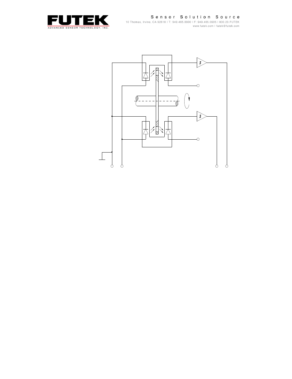
3.3. Rotation Angle Measuring System (TRD/TRH/TRS/605/705)
Fig. 6: Diagram showing the design of the rotation angle measuring system
1. Rotating Torque Shaft
2. Pulse Disk
3. Forked Light Barrier with LED and Photo Diode
4. Operation Amplifier
Features:
360 light-dark stripes on the pulse disk
Two forked light barriers shifted by phase angle 90°
Pulse number proportional to the rotation angle
This manual is related to the following products: