FUTEK TRS-Series User Manual
Page 14
14 EM1005
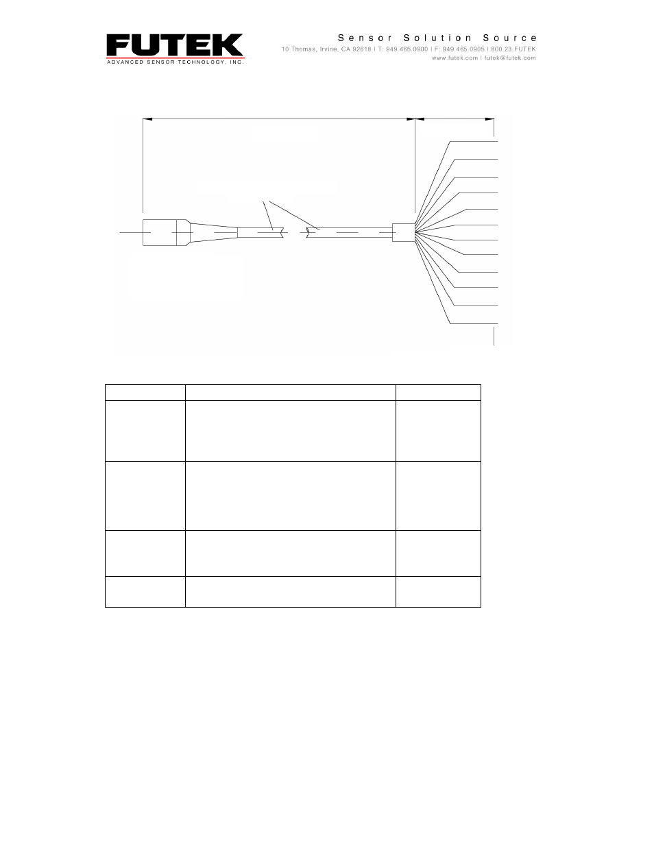
4.3.1. Cable Diagram, Plug (Sensor), Open Ends, Model ZCC911
Fig. 11: Cable Diagram, Plug (Sensor), Open Ends
Binder Pin Out
Function
Wiring Code
F
Torque, Power Supply
Red
*E
Torque, Power Supply, Ground
Black
C
Torque, Signal Output
Green
D
Torque, Signal Output, Ground
White
H
Angle, Power Supply
Orange
*E
Angle, Power Supply, Ground
Black
B
Angle 1/ Speed, Signal Output
Blue
G
Angle 2 (90° shifted to Angle 2), Signal
Output
Brown
K
Shunt Calibration, Power Supply
Purple
A
Shunt Calibration, Power Supply, Ground
Yellow
M
Shield, Inside the sensor to housing
-
J
Not Connected
-
L
Not Connected
-
12 Pin Binder
Plug
Flexible Cable
Cable Length
Pigtail
Tinned End
This manual is related to the following products: