Dwyer instruments, inc – Dwyer FS User Manual
Page 5
DWYER INSTRUMENTS, INC.
Phone: 219/879-8000 www.dwyer-inst.com
P.O. BOX 373 • MICHIGAN CITY, INDIANA 46361, U.S.A. Fax: 219/872-9057
e-mail: [email protected]
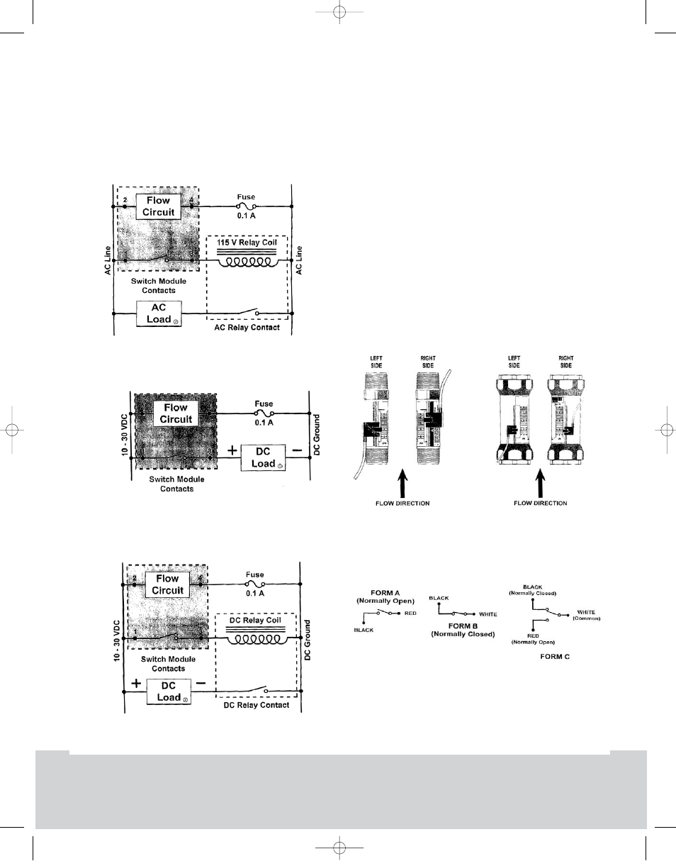
2 - AC Conventional Secondary Connections
(Figure 12):
Figure 12 demonstrates a secondary (slave) relay with a
115 VAC coil integrated with the AC switch module. This
combination allows switching of loads up to the rating of
the relay contacts.
3 - DC Conventional Connection (Figure 13):
4 - DC Conventional Secondary Connections
(Figure 14):
Flow-Alert Reed Switch Installation,
Operation, and Adjustment
Warning: All wiring should be made in accordance with
the National Electrical Code and must conform to any
applicable state and local codes.
Figure 13 depicts the correct switch orientation to ensure
secure engagement of the adjustment locking mechanism.
The drawing assumes the flow scale points to the front.
1) Install the switch on the flow meter by placing the
adjustment arm over the serrated rail from the bottom of
the meter and pushing up for 1/2, 3/4, and 1 inch meters
or pushing down from the top on 1-1/2 and 2 inch meters.
Each meter will accept up to two reed switches and the
switch(es) for 1/2, 3/4, and 1 inch meters must be
installed before the meter is plumbed into the system.
2) Flow-Alert reed switches are available in three
configurations, Form A (Normally Open), Form B (Normally
Closed), and Form C (SPDT). Wire color codes and switch
configurations are shown in Figure 16.
Figure 12
Figure 13
Figure 14
Figure 15
Figure 16
FS 12/4/03 2:15 PM Page 5