Dwyer instruments, inc – Dwyer FS User Manual
Page 4
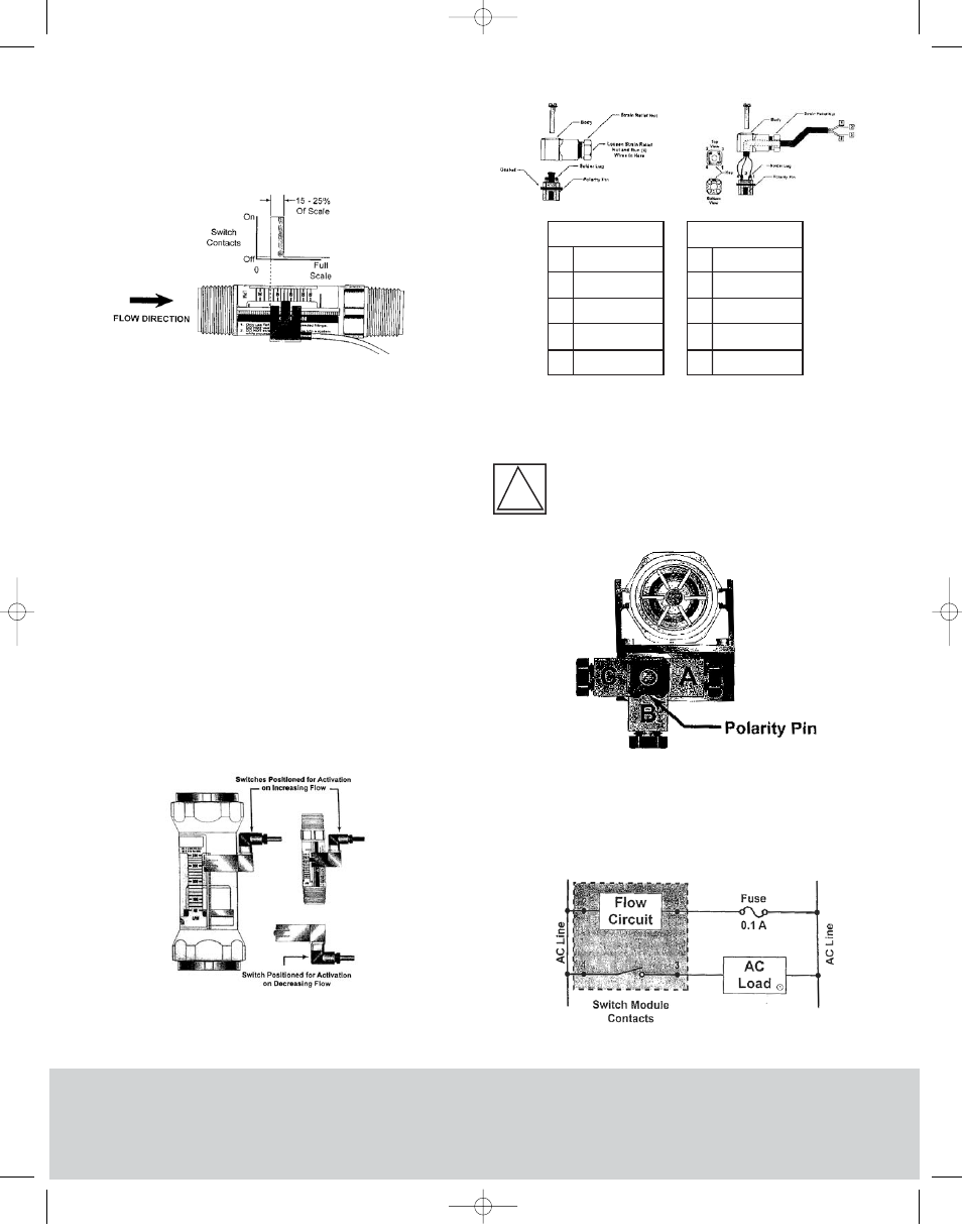
change state (See Figure 6). The set point is adjustable
from 0 to 100% of full scale. Two reed switch flow alerts
may be installed on a single flow meter but one must be
set for activation on increasing flow and the second must
be set for activation on decreasing flow.
Latching Flow-Alert Switch Installation,
Operation and Adjustment
1. Install the switch on the flow meter by placing the
adjustment arms over the serated rail from the rear of the
meter by pushing down. The direction of the connector
and cable assembly indicate whether the switch will
activate on increasing flow, connector and cable pointing
up, or on decreasing flow, connector cable pointing down.
(See Figure 7.)
2. The connector has four solder lugs labeled: 1, 2, 3 and 4.
Soldering wires to the terminals first requires disassembly of
the connector as shown in Figure 8. Figure 9 depicts the
specific wiring pinouts for each style of latching switch. It
should be noted BEFORE reassembly which wire is
connected to which solder lug. Color coding or labeling the
wires is advised.
3. After securing the wires to the solder lugs, a
determination of, “Which direction should the body of the
connector face?” needs to be made. Before snapping the
conductors back into the connector body, see Figure 10.
4. After selecting direction A, B, or C, snap connector back
together, pull the excess wire out of the strain relief, and
tighten the strain relief nut.
DWYER INSTRUMENTS, INC.
Phone: 219/879-8000 www.dwyer-inst.com
P.O. BOX 373 • MICHIGAN CITY, INDIANA 46361, U.S.A. Fax: 219/872-9057
e-mail: [email protected]
Figure 6
Reed Switches
Figure 7
Figure 8
AC - WIRING CONFIGURATIONS
Warning: All wiring should be made in
accordance with the National Electrical Code
and must conform to any applicable state and
local codes.
!
AC Switch
Function
Relay (NO)
AC Supply
Relay Common
AC Supply
Pin
1
2
3
4
DC Switch
Function
Relay (NO)
DC +
Relay Common
DC -
Pin
1
2
3
4
1 - AC Conventional Connection (Figure 11):
Note
1
: Load must be within specified contact rating range. 1 A
@ 30 VDC/500 mA @ 125 VAC.
Figure 9
Figure 10
Figure 11
FS 12/4/03 2:15 PM Page 4