Dwyer instruments, inc, Pressure drop flow-alert switch options, Flow-alert latching limit switch – Dwyer FS User Manual
Page 3: Flow-alert reed limit switch, Switch specifications, Figure 5 latching switches
CAUTION: Consult the factory before using
any polysulfone meters to monitor the
following fluids: AMMONIA, ETHYLENE
GLYCOL 50/50, PHOSPHATE ESTER,
PHOSPHATE ESTER BASE, PHOSPHORIC
ACID.
!
PRESSURE DROP
FLOW-ALERT SWITCH OPTIONS
NOTE: All flow-alert switches are magnetically triggered.
Magnets cannot be added to the basic flow meter so it
is not possible to add a switch to the basic meter if it
was not originally ordered with the switching magnet.
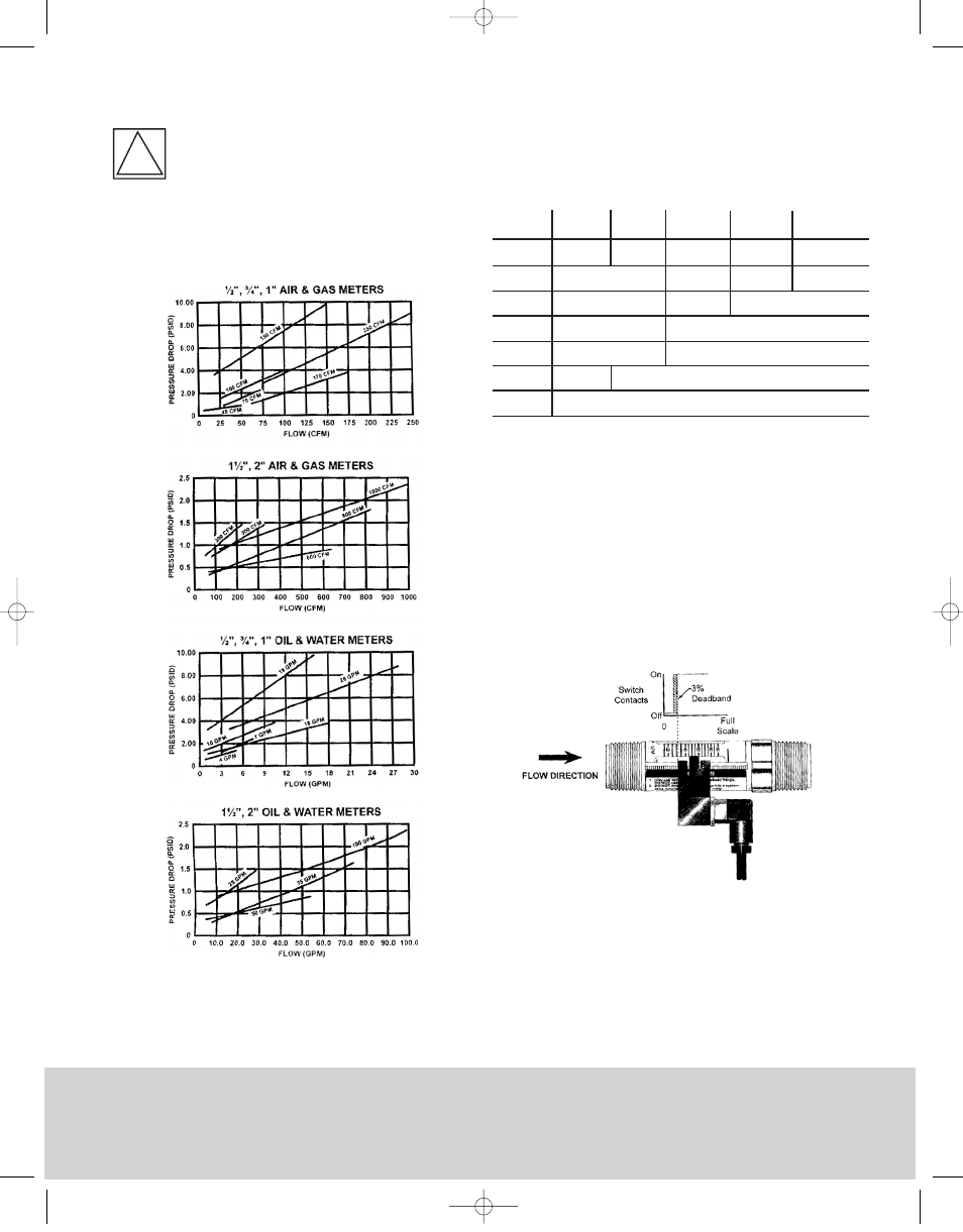
FLOW-ALERT LATCHING LIMIT SWITCH
The AC and DC powered low alert modules consist of
relay circuit housed in a sealed polypropylene enclosure.
The modules have a normally open dry relay contact that
can be used to directly control alarms, warning lights, and
relays or can be used to interface to a PLC. The relay will
be latched on as the magnet inside the flow meter passes
by the module and remained latched on until the magnet
passes in the other direction or power is interrupted (See
Figure 5). The set point is adjustable from 0 to 100% of
full scale. Flow meters can be equipped with one latching
limit switch, either AC or DC.
FLOW-ALERT REED LIMIT SWITCH
The reed switch alert modules are available in three
forms. They are: Form A (Normally Open), Form B
(Normally Closed), and Form C (SPDT). Reed switches are
housed in a sealed polypropylene enclosure for
environmental protection. the reed switch modules do not
provide a latching function like the AC and DC powered
units. When the magnet inside the flow meter comes
within proximity of the module, the reed switch will
DWYER INSTRUMENTS, INC.
Phone: 219/879-8000 www.dwyer-inst.com
P.O. BOX 373 • MICHIGAN CITY, INDIANA 46361, U.S.A. Fax: 219/872-9057
e-mail: [email protected]
Specifications
AC Latching DC Latching
Reed Switch
Form-A (N.O.)
Reed Switch
Form-B (N.C.)
Reed Switch
Form-C (SPDT)
SWITCH SPECIFICATIONS
Operating
Voltage
Operating
Current
Contact
Rating
Operating
Temp.
Cable
Certification
Enclosure
Rating
115 VAC ±10%
25 mA max
1A @ 30 VDC 0.5 @125 VAC
Resistive Load
32 to 158°F (0 to 70 °C)
Not Included
CE
3 ft., 24 ga 2 conductor PVC Jacket
32 to 250°F (0 to 125 °C)
0.25A @ 175 VDC
Resistive Load
1A @ 200 VDC
Resistive Load
N/A
N/A
NEMA 12 &13 (IP65)
N/A
N/A
N/A
N/A
N/A
10-30 VDC
Figure 5
Latching Switches
FS 12/4/03 2:15 PM Page 3