Dwyer STFLO User Manual
Page 2
RECOMMENDED PIPING
Series STFLO Stainless Steel Flowmeters generally have no special
straight run or other piping requirements. Inlet piping should be the same
size as the meter connection. Some effect on meter accuracy may occur
at high flow velocities if inlet piping guidelines are violated. Please refer
to the table on the next page. When installing on different size pipe, use
standard pipe adapters and come into the meter inlet with a nipple 8
diameters long of the same size for greatest accuracy. Control valves
should be mounted on the outlet side of the meter. The use of a three
valve manifold around the meter is suggested, as it allows uninterrupted
process flow while the meter is being cleaned.
PLUMBING-IN
While the flowmeters should be vertical, exact plumbness is not
necessary. A general rule is that if the meter appears plumb, it is close
enough (even if off by 10º, the predictable reading error is usually less
than 1%). Pipe should be cut to proper lengths to avoid stress on the
meter. Avoid over-tightening, and do no use wrenches on the body or
reading scales. If using solvents in the vicinity of reading scales, the
scales should be removed until fumes clear.
SURGE & WATER HAMMER PREVENTION
Operating Limits are for non-shock conditions only. Flowmeters are more
accurate and less likely to be damaged when the fluid flow is smooth.
Water hammer is a hazardous phenomenon and should be eliminated
from any fluid system. Water hammer is a series of pressure shocks
create by a sudden change in the flow velocity of liquid in a pipe. This
sudden change, often caused by a fast acting valve or starting, stopping,
or change in speed of a pump, generates an immediate rise in pressure
that sometimes makes a noise similar to striking the pipe with a hammer.
The pressure wave is transmitted from the source throughout the
system, subjecting every component to the sudden shock. Pressure
returns to normal only when a larger vessel or pipe section is reached,
the energy dissipated thru friction and pipe expansion, or some
component ruptures. Rupture of piping, valves, flowmeters, or other
components have obvious safety ramifications that must be addressed.
SURGE CHAMBERS & ACCUMULATORS
Flowmeters are more accurate and less likely to be damaged when the
fluid flow is smooth. If the meter must be installed on a line where
reciprocating pumps causing pulsation are used, surge chambers,
accumulators, or desurgers are strongly suggested to dampen the shock
wave. This is a good, general practice for all flowmeters.
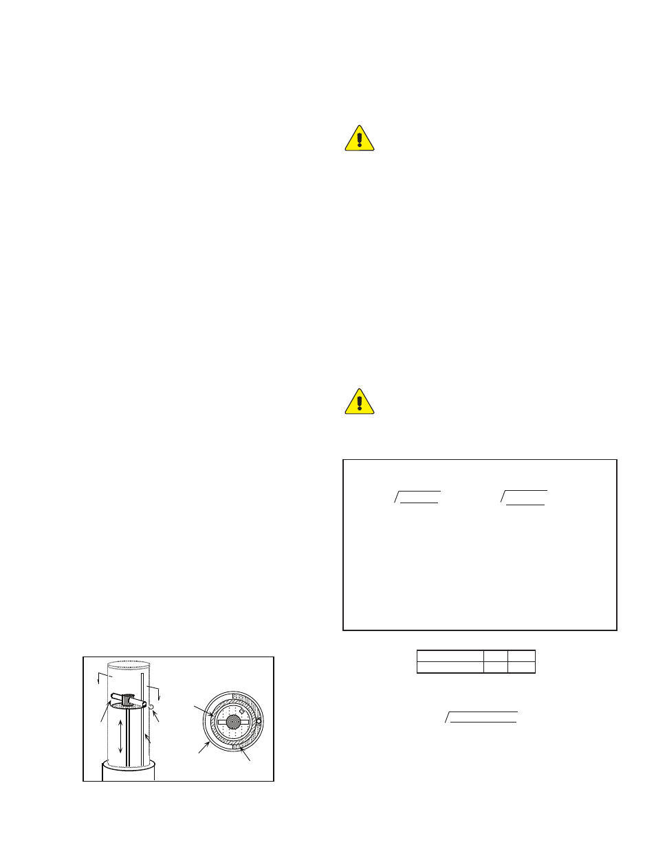
READING SCALES ROTATION
Series STFLO Stainless Steel Flowmeters use magnetically-linked ball
indicators and the scale may be positioned over approximately a 300 ˚
range. However, the magnet position must also be changed accordingly,
requiring removal of the reading scales (see “Disassembly”). On
standard STFLO Stainless Steel Flowmeters as depicted in Figure 1, the
magnet slides out of the carrier at the top of the float assembly. The
screw holding the carrier to the float may be loosened to allow rotation
of the carrier toward the desired scale location. Re-tighten the screw
(thread sealant is recommended), replace magnet, and reassemble the
meter (see “Assembly”). Verify that the ball indicator has been “captured”
by the magnet. If not, rotate the reading scales until the ball is “grabbed”
by the float magnet.
SEC A-A, TOP VIEW
METAL
PRESSURE
TUBE
PHENOLIC
RACEWAY
A
A
MAGNET
BALL
INDICATOR
SNORKEL-
GUIDE
READING
SCALES
FIGURE 1
STARTUP
System flow should be started with the bypass valve open and meter
inlet and outlet valves closed. After the system is operating, open the
meter inlet valve gradually to equalize internal pressure. Then slowly
crack meter outlet valve and wait for float to stabilize. Finally, slowly
open the meter outlet and/or flow regulating valve all the way and close
the system by-pass valve.
AVOID SUDDEN SURGES THAT CAUSE THE METER
FLOAT TO SLAM INTO THE TOP OF THE READING
SCALES!
Although not essential, the meter reading scales should be filled to a
level above the float on liquid systems. The snorkel tube (present in most
standard models) allows escape of entrapped gases except for a small
pocket in the upper end which helps cushion hydraulic shock. To assure
proper filling and to flush any foreign particles from the meter, operate
the system at full flow briefly at startup.
READING FLOW
Read flow directly from the scale as the number nearest to the center of
the ball indicator.
COMPENSATING FOR SYSTEM CHANGES
To find the correct flow reading for a system whose fluid conditions vary
from those for which the meter is scaled, use the conversion equations
provided. The most practical method of applying the formulae is to
calculate a conversion factor for the new system condition and
multiplying the scale reading by that factor. In the problems to the right,
“Q’s” has been assigned a value of “1” to determine the conversion
factor. (Dwyer Instruments, Inc. can provide special scales at additional
cost for other fluids and/or units.)
EXAMPLE: Using a standard stainless steel meter scaled for water (ps
= 1.00), what is the conversion factor for an oil with a specific gravity of
0.85?
Thus, actual flow of the oil would be the observed scale reading times
CAUTION: DO NOT OPERATE THE FLOWMETER ON A
SYSTEM EXCEEDING THE OPERATING LIMITS OF THE
UNIT. WHEN CHANGING OPERATING CONDITIONS, MAKE
SURE THAT THE NEW SYSTEM CONDITIONS ARE WITHIN
THE FLOWMETER OPERATING LIMITS, AND ALL WETTED
MATERIALS ARE COMPATIBLE WITH THE FLUID.
CORRECTING READINGS FOR NEW LIQUID CONDITIONS
Where:
Qa=Actual flow, GPM (or same units as scale)
Qs=Meter reading from scale, (scale units)
ps=Specific gravity of calibration liquid related to water in std.
atmosphere at 70˚F being 1.00
pa=Specific gravity of metered liquid, same base
ds=Density of calibration liquid, lbs/ft3
da=Density of metered liquid, lbs/ft3
pf=Specific gravity of meter float
df=Density of the meter float as per Table below
Qa = Qs
√
Ps(Pf-Pa)
Pa(Pf-Ps)
√
ds(df-da)
da(df-ds)
or Qa = Qs
FLOAT SPECIFIC GRAVITIES/DENSITIES
Material
Stainless Steel
pf
8.05
df
501.1
=1.11
Qa = 1.00
x
√
1.00 (8.05 - 0.85)
0.85 (8.05 - 1.00)