Dwyer STFLO User Manual
Dwyer instruments, inc, Series stflo stainless steel flowmeters, Bulletin f-41-stflo
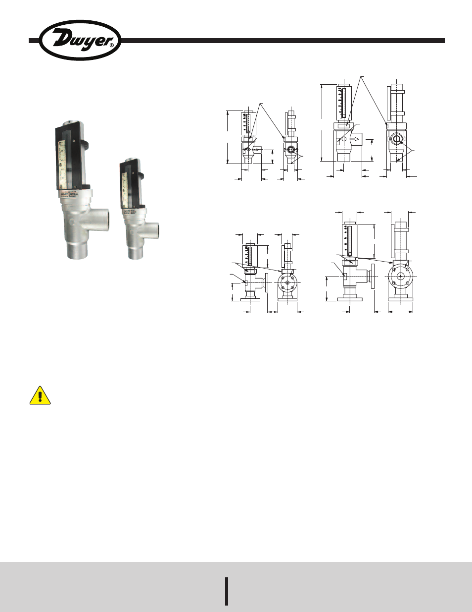
Series STFLO Stainless Steel Flowmeters
Specifications - Installation and Operating Instructions
Bulletin F-41-STFLO
Series STFLO Stainless Steel Flowmeters are ideal for dirty or
opaque fluids, high temperature and high pressure service and harsh
environments, specifically steam applications.The direct reading scale
provides ±2% accuracy. Flowmeters can quickly be disassembled
without removing the body from the pipeline for easy cleaning.
SAFETY PRECAUTIONS
Personnel safety should be considered before pressurizing and
operating the system. There are numerous possibilities for
error in system operation and maintenance as well as
component installation. Because human eyes must necessarily
come into close proximity with the flowmeter to read it, Dwyer
Instruments, Inc. recommends that safety shielding such as a
sheet of transparent, high impact material be used in front of
the meter. If hazardous, toxic, or flammable fluids are being
metered, recommended safeguard should include methods to
protect personnel from splash or rebound. A method of quick,
safe removal of dangerous fluids should also be included.
INSTALLATION
PREPARATION: Series STFLO Stainless Steel Flowmeters are ready to
install as-is, although the reading scales may need repositioning so the
scale is visible after installation. First, remove the protective caps from
the connection ports. Also, remove the plastic tubing above the inlet cap
in the meter core tube! This tubing blocks the float assembly in place
during shipment. Check that the float moves freely within the core tube,
and that no packing materials are in the meter.
DWYER INSTRUMENTS, INC.
Phone: 219/879-8000
www.dwyer-inst.com
P.O. BOX 373 • MICHIGAN CITY, INDIANA 46360, U.S.A. Fax: 219/872-9057
e-mail: [email protected]
SPECIFICATIONS
Service: Compatible with liquids and gases.
Wetted Material: T316 SS, Alnico magnet, PTFE.
Temperature Limits: See chart on page 7.
Pressure Limits: See chart on page 7.
Accuracy: ±2% FS.
Repeatability: ±0.5% of indicated flow rate.
Process Connections: 3/4˝ or 1-1/2˝ female NPT, optional flange
connections.
Scale Length: 3/4˝ models: 3.2˝ (8 cm); 1-1/2˝ models: 5.2˝ (13 cm).
Weight: 3/4˝ NPT models: 5.75 lb (2.6 kg); 1-1/2˝ NPT models: 14 lb (6.4
kg). 3/4˝ Flange: 9.75 lb (4.4 kg); 1-1/2˝ Flange: 22 lb (10 kg).
4-1/32
[102.25]
2-11/16
[68.07]
IN
10-21/32
[270.78]
LABEL, SEE
DETAIL 1
3/4 NPT CONNECTION
OUT
2-13/16
[71.37]
LABEL
SEE
DETAIL 2
2-3/4
[69.95]
Ø1-11/32
[34.29]
3/4 NPT
15-21/32
[397.28]
LABEL SEE
DETAIL 1
LABEL, SEE
DETAIL 2
IN
OUT
4-1/2
[114.38]
3-23/32
[94.23]
5-11/16
[144.65]
1-1/2 NPT
Ш2-15/32
[62.99]
Ш4
[101.85]
1-1/2 NPT CONNECTION
3
[76.20]
LABEL, SEE
DETAIL 1
LABEL, SEE
DETAIL 2
5
[127.00]
4-31/32
[125.98]
5
[127.00]
6-13/16
[172.97]
3-1/2
[88.91]
Ш3-7/8
[Ш98.55]
Ш2-3/4
[Ш69.85]
2-1/8
[53.59]
3
[76.20]
4-1/2
[114.30]
LABLE, SEE
DETAIL 1
LABEL, SEE
DETAIL 2
3-11/16
[93.73]
3-9/16
[90.43]
3-7/8
[98.55]
3/4 FLANGE CONNECTION
1-1/2 FLANGE CONNECTION