Page 8 page 9 parts list, Operation – Dwyer TBS User Manual
Page 6
Page 8
Page 9
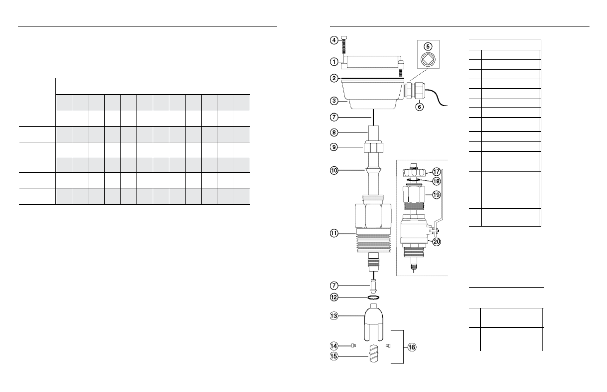
PaRTS lIST
TBs-0XX Parts
1
Upper housing assembly
2
Housing Gasket
3
Lower housing
4
Housing screw assembly
5
Plug, steel
6
Strain relief
7
Sensor w/cable
8
Tube
9
Compression nut
10
Compression Ferrule
11
Adapter fitting
12
Rotor housing O-ring
13
Rotor housing
14
Jewel bearing assembly
(for carbide shaft)
15
Turbine Rotor assembly
16
Rotor repair kit
(consists of #14 & #15)
(0.5)
(1.0)
(2.0)
(5.0)
(10.0)
(20.0)
(30.0)
TABle 4: Flow Rates converted from Feet/sec to Gallons/minute at various velocities: schedule 40 pipe
Nominal pipe size
Feet / sec
▲
3" 4" 6" 8" 10" 12" 16" 24" 30" 36" 38" 40"
11.5
19.8
45
78
123
176
313
704
1100
1585
1770
1960
23
39.7
90
156
246
349
551
1250
2200
2910
3530
3915
46.1
79.4
180
312
492
698
1100
2510
4401
5830
7070
7825
115
198
450
780
1230
1740
2750
6270 11002 14570 17670 19560
230
397
900
1560
2460
3490
5510
12530 22005 29140 35350 39120
461
794
1800
3120
4920
6980
11020 25060 44010 58270 70700 78240
691
1190
2700
4680
7370
10470 16520 37600 66015 87410 106050 117500
flow Range.
These sensors are designed to operate at flow
velocities of 0.5 to 30 feet per second (see Table 2, below).
If erratic readings are encountered at low flows, check the
chart to see if flow is below minimum for the pipe size. The
standard shaft and bearings should have a long life at continu-
ous high flow.
TBs-1XX Parts (hot-tap)
All part numbers are the same except those
below
17
Locking Collar
18
Adapter fitting O-ring
19
Adapter, hot tap
20
Valve assembly
(inlcudes Adapter, #20)
oPERaTIon
TX101/201
TX115/215
TBS-0XX
TBS-1XX