Dwyer TBS User Manual
Page 2
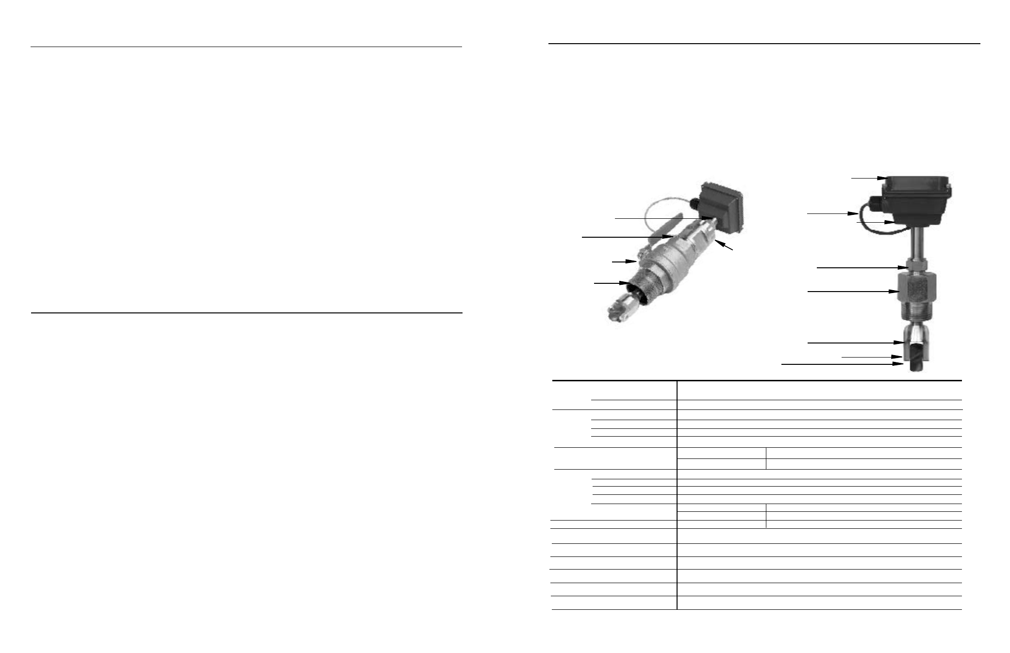
Rotor
Rugged cast aluminum housing
18 Foot Cable
Modular electronics (optional)
• rate/total/pulse/4-20 mA
(Series RTI)
• blind 4-20 transmitter
(Series BAT)
Compression nut
for easy adjustment, secure locking
Adapter fitting
with 1-1/2” NPT threads
Rotor housing
Removable jewel bearings
TBS-0XX
Adapter fitting
with 2” NPT threads
Full-port 2” ball valve
for sensor removal
2” Adapter
removes to mount
hot-tap machine
3/4” diameter tubing
for low insertion force
TBS-1XX
Locking collar
TaBlE of ConTEnTS
General Information
Features, Specifications .......................................................................................................................................Page 1
Installation
Piping, Immersion, Positioning the Meter ...........................................................................................................Page 2
Straight Pipe Recommendations .........................................................................................................................Page 3
Full Pipe Recommendations .................................................................................................................................Page 4
Fitting Installation, Meter Installation ..................................................................................................................Page 5
Proper Depth Setting, Dimension C, Pipe Wall Thickness ..................................................................................Page 6
Set-Up
Connection, Calibration, K-Factors ......................................................................................................................Page 7
operation
Flow Range, Flow Rates ........................................................................................................................................Page 8
Parts list
Parts Exploded View..............................................................................................................................................Page 9
Troubleshooting & Repair
Troubleshooting, Repair, Rotor Replacement ......................................................................................................... Back
TaBlES anD DIaGRaMS
Features ................................................................................................................................................................ Page 1
Specifications ....................................................................................................................................................... Page 1
Positioning the Meter ........................................................................................................................................... Page 2
Piping .................................................................................................................................................................... Page 2
Straight Pipe Recommendations ........................................................................................................................Page 3
Full Pipe Recommendations ................................................................................................................................ Page 4
Meter Installation ................................................................................................................................................. Page 5
Depth Setting ....................................................................................................................................................... Page 6
Pipe Wall Thickness ............................................................................................................................................. Page 6
Connection Diagram ............................................................................................................................................ Page 7
Parts Exploded View............................................................................................................................................. Page 9
Parts List ............................................................................................................................................................... Page 9
Rotor Replacement ..................................................................................................................................................B a c k
Page 1
GEnERal InfoRMaTIon
The Series TBS is an adjustable depth insertion turbine that
comes in brass or 316 stainless models to fit 3” to 40” pipe.
Installation fittings are standard 1-1/2" (TBS-XSX Models) or
2” (TBS-XLX Models) male NPT. Fittings such as saddles and
weldolets may be purchased either locally or from Dwyer Instru-
ments Inc. Please see Series SDF.
Ruby bearings and a non-drag pickoff give these adjustable
insertion turbine flow sensors a wide flow range and long life.
A sensor detects the passage of miniature magnets in the ro-
tor blades. The resulting square-wave signal can be sent for
hundreds of feet without a transmitter, over unshielded cable.
This signal can be connected directly to many PLC’s and other
controls without any additional electronics.
If desired, a modular system of electronics can be installed
directly on the flow sensor or mounted remotely. The Series
RTI (loop powered) provides digital rate and total display, as
well as programmable pulse. The Series RTI also provides a
4 to 20 mA analog output. The BAT is a blind analog (4 to 20
mA) transmitter. Programmable pulse for pump pacing is
available with the PWD.
The “hot-tap” models can be installed or serviced without shut-
ting down the line by means of a 2” full-port isolation valve
that comes with a nipple for installation on the pipe fitting. In
most circumstances, no special tool is required.
fEaTURES
SPECIfICaTIonS*
6-40 Vdc
< 2 mA
Magnetoresistive
Current Sinking Pulse
100 mA max
3 to 40 Vdc
-S Model
-l Model
3” - 12” (50 - 300mm)
12” - 40” (300 - 890mm)
Cast aluminum
Brass or 316 SS
PVDF standard
Nickel-bound tungsten carbide/Ruby
TBS-0
TBS-1
None
Bronze (316SS optional)
1-1/2” NPT
2” NPT
0.5 - 30 feet/sec (0.15 - 9.14 meter/sec)
+/-1.5% of full-scale
200˚ F (93˚ C)
200 psi (14 bar)
0.44 x pressure in pipe
#22 AWG 3-con, 18’ (6m); 2,000’ (650m) maximum cable run
Power
Supply Voltage
Current
Sensor Type
output
Sinking Current
External Pull-up Resistor
Pipe Size
Materials Housing
Sensor Body
Rotor
Shaft/Bearings
Isolation Valve
fitting Size
flow Range
accuracy
Maximum Temperature
Maximum Pressure
Insertion force
Cable
*Specifications subject to change.
Note: For larger pipe sizes contact Dwyer