Dwyer TBS User Manual
Page 4
Page 4
InSTallaTIon
InSTallaTIon
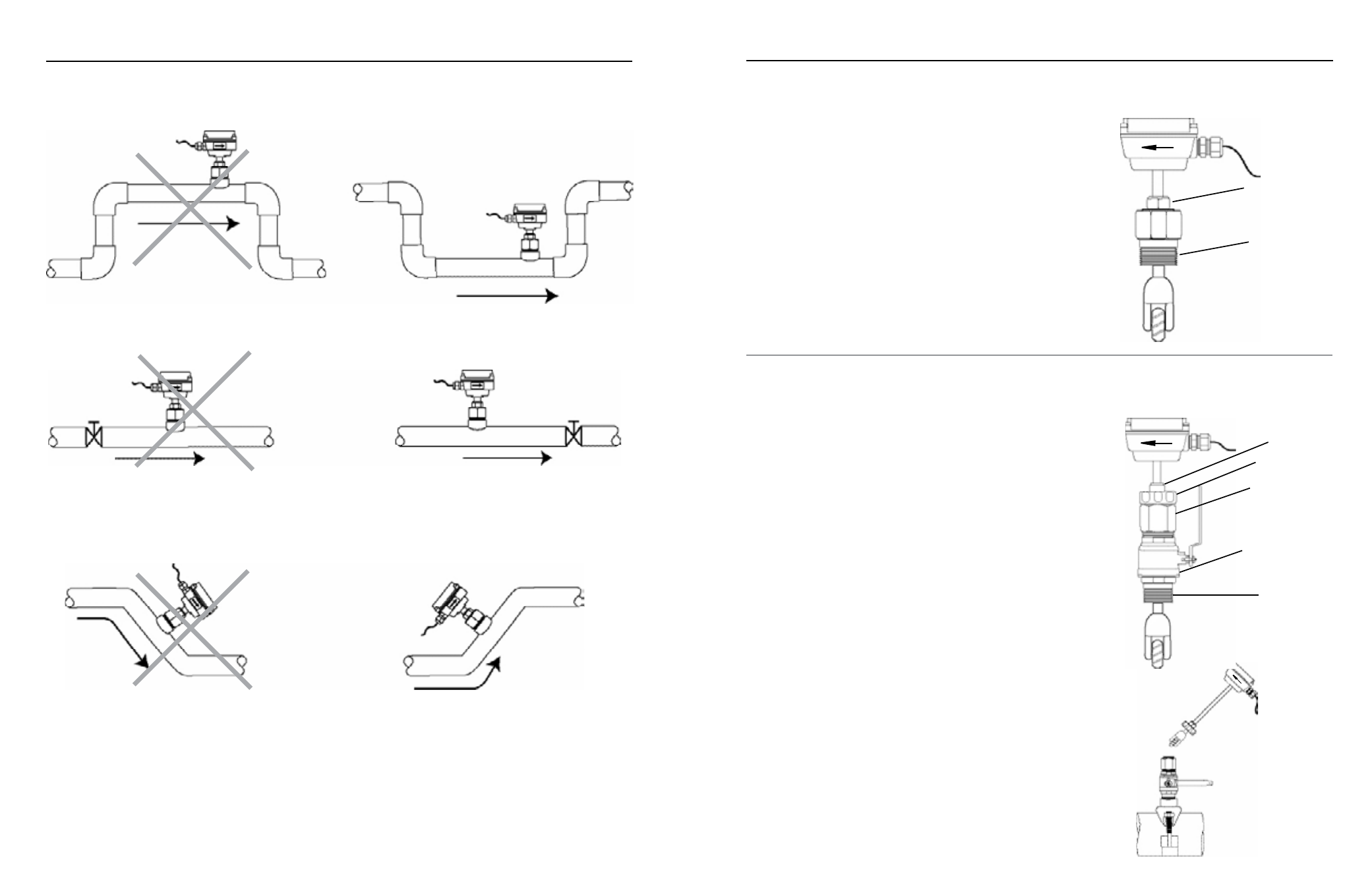
fUll PIPE RECoMMEnDaTIonS
Allows air pockets to form at sensor
Ensures full pipe
Post-valve cavitation can create air pocket
Keeps pipe full at sensor
Air can be trapped
Allows air to bleed off
Page 5
Better Installation
Possible Problem
Better Installation
Possible Problem
Better Installation
Possible Problem
TBS-0XX InSTallaTIon
fitting Installation.
TBS-0XX sensors come with a 1-1/2” male NPT pipe
thread adapter fitting. Any fitting that provides the matching NPT female
thread may be used. (For comparable saddle fitting please see Series
SDF.) Installation procedure compensates for fitting height differences.
Cut a minimum 1-3/4” hole in the pipe. If possible, measure the wall
thickness and write it down for use in depth setting. Then install the
threaded fitting (saddle, weldolet, etc.) on the pipe.
Meter Installation.
Loosen the compression nut so that the adapter slides
freely. Pull the meter fully upward and finger-tighten the compression
nut. Using a thread sealant, install the adapter in the pipe fitting. Do
not overtighten. Loosen the compression nut and lower the meter to
the appropriate depth setting (see diagram and instructions that follow).
Caution: Do not allow the meter to fall into the pipe uncontrolled, as this
may damage the meter. Be sure flow is in the direction of the arrow on
the housing. Tighten compression nut fully.
TBS-1XX InSTallaTIon
‘Hot-tap’ meters are designed to be installed and serviced without
depressurizing the pipe.
fitting Installation.
The hot-tap sensors have a 2” male NPT thread for
compatibility with the 2” isolation valve. Any fitting that provides matching
NPT female thread may be used. The installation procedure compensates
for differences in fitting height.
If initial installation is performed on an unpressurized pipe, cut a
minimum 1-3/4” hole in the pipe. If possible, measure the wall thickness
and write it down for use in depth setting. Then install the threaded fitting
(saddle, weldolet, etc.) on the pipe. (Such as the Series SDF.)
If it is necessary to do the initial installation under pressure, any standard
hot-tap drilling machine with 2” NPT adapter, such as a Transmate or a
Mueller, can be used. Ordinarily, it is not necessary to use an installation
tool, since the small-diameter tube can be controlled by hand but should
be used for higher pressures.
Meter Installation.
Remove the sensor unit from the valve assembly.
Using a thread sealant, install the valve assembly on the pipe fitting. If
the initial installation is a pressure (“hot-tap"), remove the 1-1/2” x 2”
adapter bushing at the back of the valve. Thread the tapping machine
on, open the valve, and tap using a minimum of 1-3/4” or maximum
1-7/8” cutter. After retracting the machine and closing the valve, reinstall
the flow sensor. When the sensor is secure, open the valve and adjust
depth setting (see diagram and instructions that follow). Be sure flow is
in the direction of the arrow on the housing. Tighten locking collar and
compression nut fully.
Compression nut
Adapter fitting
with
standard 1-1/2"
NPT threads
Compression nut
2” adapter removes
to mount hot-tap
machine
Full-port 2” ball
valve allows sensor
removal
Standard 2”
NPT threads
TBS-1XX Sensor
Removal
Locking collar
TBS-0XX