Fig. a – Dwyer DH3 User Manual
Page 3
INSTALLATION
LOCATION: Select a clean, dry location free from shock and vibration where temperature
limits will not be exceeded. Distance from the transmitter to the receiver is limited only by
total loop resistance. See ELECTRICAL CONNECTIONS. Tubing feeding pressure to the
instrument can be practically any length required, but long lengths will increase response
time slightly.
POSITION: All standard models are calibrated for use in a vertical mounting position.
Higher range models will perform properly at other angles but should be spanned and
zeroed in the position in which they will be used. Because of their sensitivity to gravitation-
al forces, models with ranges under 1˝ w.c. (25.4 mm w.c.) must always be mounted ver-
tically.
PRESSURE CONNECTIONS: For installation convenience two sets of 1/8˝ female NPT
pressure ports are supplied. Be sure to seal the unused ports with pipe plugs included.
Positive Pressure - Connect tubing to HIGH PRESSURE port and vent LOW PRESSURE
port to atmosphere.
Negative (Vacuum) Pressure - Connect tubing to LOW PRESSURE port and vent HIGH
PRESSURE port to atmosphere. (When operating this device in a dusty environment,
install an optional A-331 Filter Vent Plug in the vented port to keep interior clean.)
Differential Pressure - Connect tubing from the higher source to HIGH PRESSURE port
and from the lower source to LOW PRESSURE port.
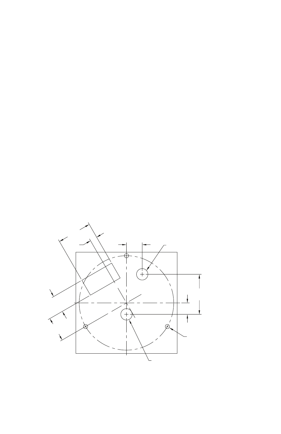
3
1-1/2
[38.1]
5/16
[7.94]
11/16
[17.46]
3/4
[19.05]
1-3/32
[27.78]
1-3/4
[44.45]
1/2 [12.70]
(3) Ø3/16 [4.77] HOLES EQUALLY
SPACED ON A 4-1/8 [104.78] B.C.
Ø1/2 [12.70] HOLE FOR
LOW PRESSURE CONNECTION
Ø1/2 [12.70] HOLE FOR
HIGH PRESSURE CONNECTION
Fig. A