Dwyer EDPS User Manual
Dwyer instruments, inc, Installation and operating instructions, Bulletin e-80-edps
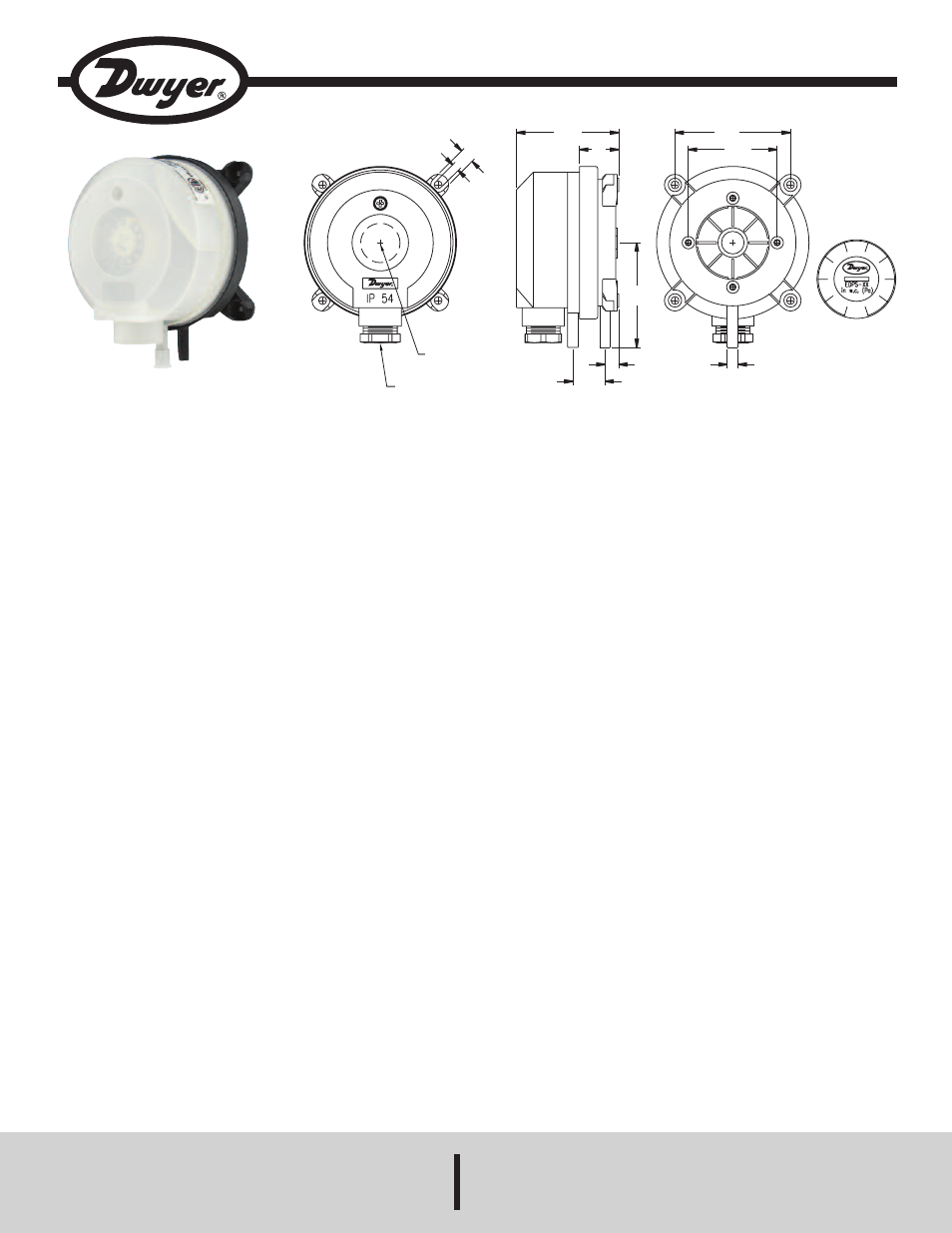
Series eDpS adjustable Differential pressure Switch
installation and operating instructions
Bulletin e-80-eDpS
the Series eDpS adjustable Differential pressure Switch is
designed for overpressure, vacuum, and differential pressure
applications. The scaled adjustment knob allows changes to the
switching pressure to be made without a pressure gage. The EDPS is
available with settings from 0.08˝ w.c. (20 Pa) to 16˝ w.c. (4000 Pa). The
silicone diaphragm and PA 6.6 body make the Series EDPS perfect for
use with air and other noncombustible gases. The Series EDPS can be
used in monitoring air filters, ventilators, and industrial cooling-air circuits
along with controlling air and fire-protection flaps and many other
applications.
Adjustable differential pressure switches are for monitoring
overpressure, vacuum and differential pressure of air or other
noncombustible, non-aggressive gases. Possible fields of application
include:
• Monitoring air filters and ventilators
• Overheating protection for fan heaters
• Controlling air and fire-protection dampers
• Monitoring industrial cooling air circuits
• Monitoring flows in ventilation ducts
• Frost protection for heat exchange
Use only with mediums such as air, or other noncombustible or non-
aggressive gases. Otherwise operating faults or accidents may occur.
Mounting
First check the pressure switch to ascertain whether any damage is
visible on the housing. If the housing is leaky because of damage, the
pressure switch must not be used.
Switching pressure specifications apply to vertical installation which is
also the recommended position with pressure connections pointing
downwards. If the switches are installed horizontally with AMP
connection terminals, the switching values are approximately 0.08 in w.c.
(20 Pa) higher.
a) Mounting Position
1. You should mount the pressure switch vertically, with
pressure connections pointing downwards. Only then is it
possible to drain any condensation moisture, which might
occur.
Only if there is no potential for condensate forming can you mount the
pressure switch horizontally. In this case, however, the switching values
are approximately 0.08 in w.c. (20 Pa) higher as indicated on the scale.
In the horizontal position, the pressure switch should be mounted ‘lying
down’ only, that is to say with the electrical connections pointing
upwards. Do not mount the pressure switch in a hanging position (that is
to say, not ‘overhead’ with the electrical connections pointing
downwards). Otherwise the device will function inaccurately.
b) Mounting with Screws or Brackets
1. To mount the pressure switch, L-shaped A-288 and S-
shaped A-289 mounting brackets can be ordered
separately. To secure the device on the rear side of the
housing, only use the sheet metal screws (3.5 x 8 mm)
which are supplied together with the mounting brackets.
Under no circumstances must you use longer screws.
Otherwise, the base of the housing could be punctured
resulting in the pressure switch leaking.
2. Alternately you can also use the snap-on brackets - to
remove it pull upwards.
3. You can also mount the pressure switch directly on a wall.
To do this use screws with a maximum diameter of 0.315˝
(8.0 mm), if you use the outer mounting lugs to screw the
device in place. Do not tighten the screws so much that the
base of the device is deformed. Otherwise, the pressure
switch can be shifted out of position, or leak.
DWYeR inStRUMentS, inc.
phone: 219/879-8000
www.dwyer-inst.com
p.o. BoX 373 • MicHiGan citY, inDiana 46360, U.S.a.
fax: 219/872-9057
e-mail: [email protected]
SpecificationS
Service: Air and noncombustible, compatible gases.
Materials: Diaphragm Material: Silicone. Housing Material: Switch
Body: PA 6.6, Cover: Polystyrene. Materials UL94 V0 Rated.
temperature Limits: Process ambient temperature from -4 to 140°F
(-20 to 60°C).
pressure Limits: Max. Operating Pressure: 40” w.c. (10 kPa) for all
pressure ranges.
Switch type: Single-pole double-throw (SPDT).
electrical Rating: Max.1.0 A/250 VAC, 50-60 Hz, max switching rate:
6 cycles/min.
electrical connections: Push-on screw terminals. 1/2˝ NPT
connection. M20x1.5 with cable strain relief optional.
process connections: 5/16˝ (7.94 mm) outside diameter tubing, 1/4˝
(6.0 mm) inside diameter tubing.
Mounting orientation: Vertically, with pressure connections pointing
downwards.
Mechanical Working Life: Over 106 switching operations.
Weight: 5.6 oz (160 g).
enclosure Rating: NEMA 13, IP54.
agency approvals: CE; ETL approved to UL508 and CSA C22.2#14.
Ш11/64
[Ш4.5]
21/64
[8.5]
2-17/64
[57.5]
7/8
[22]
2-21/64
[59]
19/64
[7.5]
51/64
[18]
-
(P2)
REMOVABLE CONNECTOR
1/2 NPT OR M20 X 1.50
ADJUSTMENT
KNOB LOCATION
+
(P1)
Ш15/64
[Ш6]
ADJUSTMENT KNOB
SCALE 2:1
2-9/16
[65]
1-31/32
[50]