Caleffi 5351 User Manual
Page 3
Installazione - Installation - Einbau - Installation -
Instalación - Instalação - Installatie
1) Prima dell’installazione del riduttore di pressione, aprire tutti i
rubinetti di erogazione per pulire l’impianto ed espellere l’aria
rimasta nelle tubazioni.
2) Installare le valvole di intercettazione a monte e valle per facilitare
le operazioni di manutenzione.
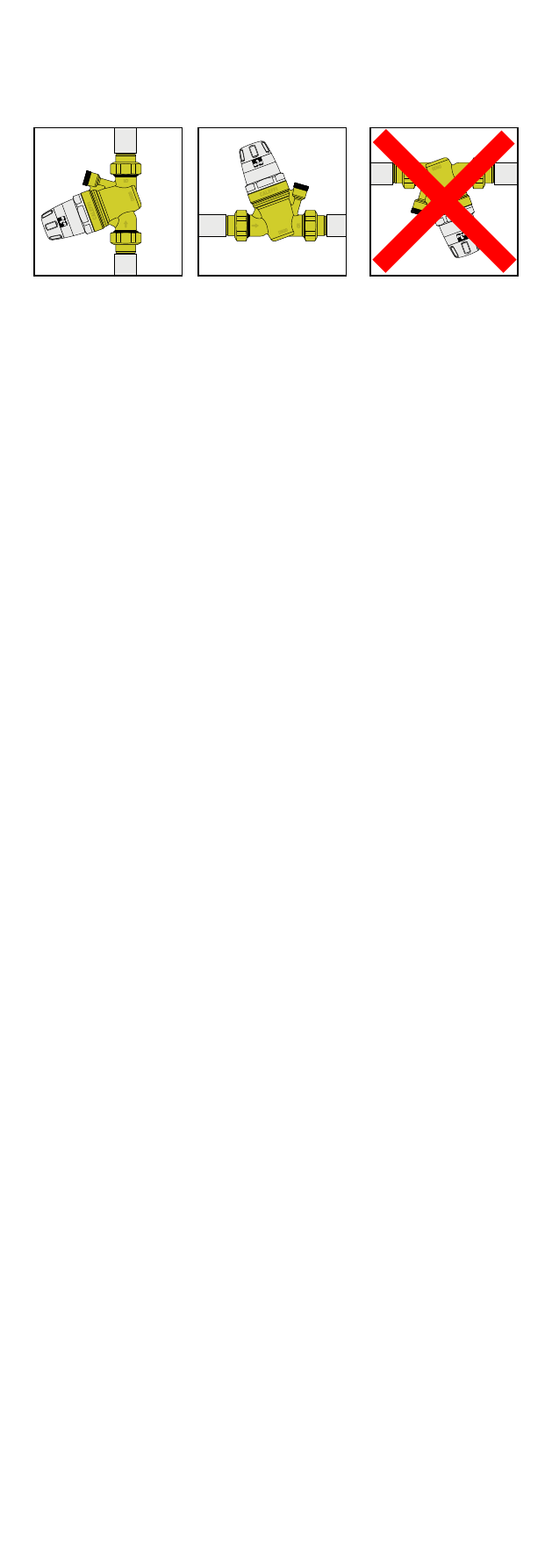
3) Il riduttore di pressione può essere installato sia con tubazione
verticale che orizzontale. E’ tuttavia indispensabile che non sia
capovolto.
4) Chiudere la valvola di intercettazione a valle.
5) Il particolare sistema di preregolazione meccanico con manopola
di manovra ed indicatore della pressione visibile sui due lati,
permette di eseguire la taratura del riduttore al valore desiderato
in impianto prima dell’installazione. Questo indicatore di
pressione ha la particolarità di avere un avanzamento a scatti
sensibili, pertanto la pressione può essere regolata in modo
continuo visualizzandone il valore ad incrementi di 0,5 bar.
6) Effettuare la taratura agendo sulla manopola di manovra posta
nella parte superiore del dispositivo. I riduttori sono preregolati di
fabbrica ad una pressione di 3 bar.
7) Data la funzione di preregolazione, la presenza del manometro a
valle dell’apparecchio non è indispensabile.
8) Dopo
l’installazione,
il
meccanismo
interno
regolerà
automaticamente la pressione, fino a portarla al valore impostato.
9) Riaprire lentamente la valvola di intercettazione a valle.
1) Before installing the pressure reducer, open all the outlets to
flush the system and expel any air left in the pipework.
2) Install shut-off valves upstream and downstream to facilitate
maintenance operations.
3) The pressure reducer can be installed in either vertical or
horizontal pipework. However it must not be installed upside down.
4) Close the downstream shut-off valve.
5) This mechanical pre-setting system, with adjustment knob and
pressure indicator visible on both sides, makes it possible to
set the reducer to the required value in the system before
installation. The pressure indicator has an incremental
movement, so that the pressure can be adjusted continuously,
displaying the value at 0,5 bar increments.
6) Calibration is carried out by means of the adjusting knob on the
upper part of the device. The reducers are pre-set at the factory
to a pressure of 3 bar.
7) In view of the pre-setting function, the installation of a pressure
gauge downstream of the appliance is not essential.
8) After installation, the internal mechanism will automatically adjust
the pressure until it reaches the required value.
9) Reopen the downstream shut-off valve slowly.
1) Vor dem Einbau alle Absperrorgane aufmachen um die Anlage
zu säubern und die restliche Luft aus den Rohren zu lassen.
2) Vor und hinter dem Druckminderer jeweils ein Absperrventil
einbauen.
3) Der Druckminderer kann senkrecht und waagerecht eingebaut
werden. Es ist jedoch sehr wichtig dass er nicht „kopfüber“
eingebaut wird.
4) Das Absperrventil hinter dem Druckminderer schliessen.
5) Das besondere mechanische Vorregelungssystem, mit der
Druckanzeige auf beiden Seiten des Griffs, gibt dem Kunden
die Möglichkeit, den Druck schon vor der Montage auf den
gewünschten Wert einzustellen. Das Besondere an dieser
Druckanzeige ist, dass sie einen schnapperartigen Vorschub
hat - somit hat der Kunde die Möglichkeit den Druckanstieg, mit
einer Einstellpräzision von 0,5 bar, visuell zu kontrollieren.
6) Die Abgleichung mit dem oberen Handgriff vornehmen. Die
Druckminderer sind bereits mit 3 bar voreingestellt.
7) Da die Möglichkeit der Voreinstellung besteht, ist das Manometer
nicht unbedingt nötig.
8) Nach dem Einbau bringt der interne Mechanismus den Druck
automatisch auf den gewünschten Wert.
9) Das Absperrventil hinter dem Druckminderer wieder langsam
öffnen.
3