Installation manual, Typical sump installation diagrams – Blue Angel Pumps SSBCS100 User Manual
Page 2
INSTALLATION MANUAL
CAUTION INDICATES A POTENTIALLY HAZARDOUS
SITUATION WHICH, IF NOT AVOIDED, MAY RESULT
IN MINOR OR MODERATE INJURY.
TO REDUCE THE RISK OF HAZARDS THAT
CAN CAUSE INJURY OR PROPERTY DAMAGE,
OBSERVE THE FOLLOWING WARNINGS:
IF THIS PUMP CONTAINS A SWITCH FOR AUTOMATIC
OPERATION, IT IS THE INSTALLER’S RESPONSIBILITY
TO MAKE SURE THE SWITCH IS ABLE TO OPERATE
WITHOUT ANY OBSTRUCTIONS WITHIN THE BASIN. It is
recommended that the installer test and observe the pump’s
operation for several cycles after installation.
IT IS RECOMMENDED TO USE RIGID PIPING AND
FITTINGS to secure the pump in the basin and reduce pump
movement. Pump movement can prevent the switch from
operating correctly.
THIS PUMP SHOULD BE INSPECTED 3 TO 4 TIMES PER
YEAR for pump movement or buildup of debris on the switch or
fl oat. Reposition pump if it has moved. Remove any debris that
could interfere with the operation of the switch.
2
IT IS RECOMMENDED TO USE A CHECK VALVE with this
pump to prevent the back-fl ow of fl uid after each pump cycle.
DO NOT INSTALL OR OPERATE THE PUMP IF IT HAS
BEEN DAMAGED IN ANY WAY.
DO NOT LIFT OR CARRY THE PUMP BY THE POWER
CORD. Use the pump’s handle.
DO NOT USE THIS PUMP IN MUD, SAND, CEMENT, OIL
OR CHEMICALS.
DO NOT USE SUMP AND EFFLUENT PUMPS TO HANDLE
RAW SEWAGE.
AN INDEPENDENT HIGH WATER ALARM OR BACK UP
PUMP SHOULD BE USED when risk of property damage from
high water levels exists
THE SWITCH SHOULD BE REPLACED EVERY TWO (2)
YEARS. This maintenance will reduce the risk of improper
pump operation, switch failure, or fl ooding.
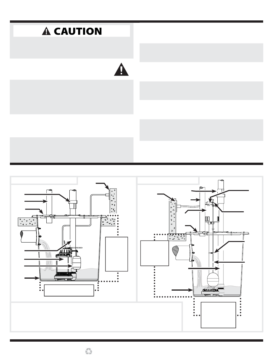
Figure 1: Submersible Sump
Figure 2: Pedestal Sump
1
2
3
5
8
9
7
6
1. GFCI
OUTLET
5. PIPE
INLET
9. SUMP
BASIN
2. CHECK VALVE
6. DISCHARGE PIPE
10. FLOAT ROD
3. VENT PIPE
7. SUMP PUMP
11. FLOAT GUIDE
4. GASKET/BASIN LID 8. SWITCH (SEE CHART A, ON PAGE 3)
12. SWITCH ARM
MINIMUM
BASIN
HEIGHT
(SEE
CHART A,
COLUMN B)
MINIMUM BASIN DIAMETER
(SEE CHART A, COLUMN A)
4
MAXIMUM
BASIN HEIGHT
(SEE CHART B,
COLUMN B)
MINIMUM BASIN
DIAMETER
(SEE CHART B,
COLUMN A)
8
6
2
3
7
9
11
5
12
10
4
TYPICAL SUMP INSTALLATION DIAGRAMS
Printed on 100% Recycled Paper
1