Electrical installation, Figure 4 - flow meter terminal functions – Badger Meter Vortex Meters User Manual
Page 9
9
09-VRX-UM-00408 07/12
The RNL Series fl ow meters are designed to mount on a standard ANSI 150 lb., 2” pipe fl ange. It is recommended that the customer
conduct a fl ow profi le survey and place the probe at the optimum point. The labeling of the fl ow direction on the sensor should
be aligned with the fl ow in the pipe. Maximum insertion depth is a product of pipe size and fl uid velocity, see Appendix Table
A1 for Insertion Depth Chart.
CAUTION: Avoid bending the vortex strut or damaging the transducers during installation. The torque value for
the Conax fi tting is 90-100 ft. lbs.
NOTE: See Appendix for further information on installation.
ELECTRICAL INSTALLATION
TP1
TP2
TP3
4-20
Pulse
XMIT
RECV
LOOP POWER
CONNECTIONS
TRANSDUCER
CONNECTIONS
PULSE
OUTPUT
R
Label Denoting
Receiving
Transducer Cable
White
Black
Green
Black
Green
White
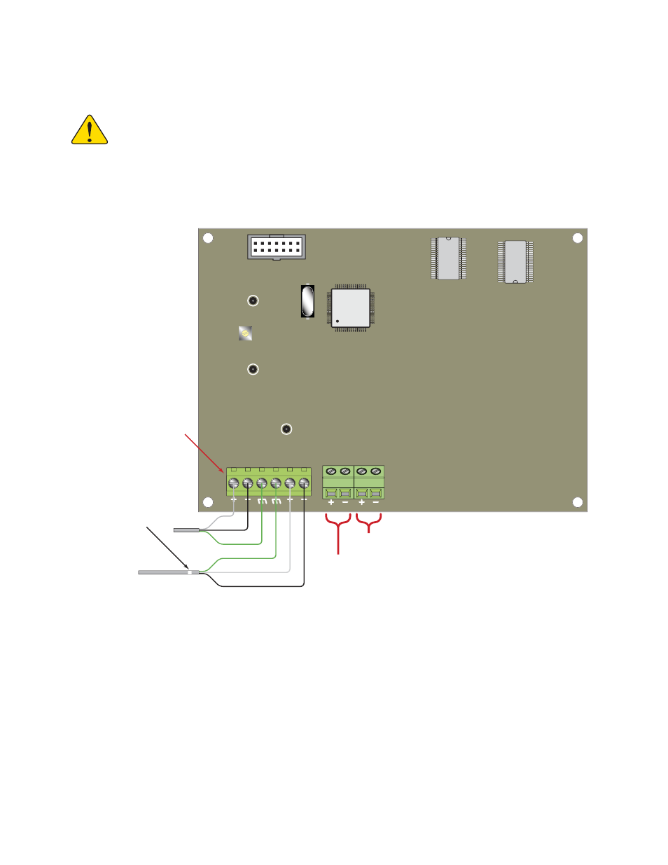
FIGURE 4 - FLOW METER TERMINAL FUNCTIONS
Electrical connections for the fl ow meter are made using screw-type terminals located inside the electronics enclosure. To
expose these terminals, open the cover. The functions of these terminals are illustrated in Figure 4.