Badger Meter Vortex Meters User Manual
Page 23
23
09-VRX-UM-00408 07/12
Maximum Fluid Velocity
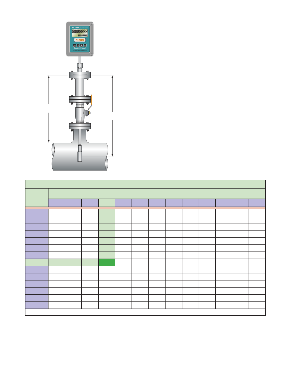
Insertion meters are subject to damage from bending if the fl uid velocity
exceeds a specifi c value. The threshold velocity where damage may occur is
found in a lookup table (See Table A1) and the depth the meter stem
extends into the pipe (See Figure A6).
L1 = Distance from bottom of fl ow meter fl ange to center of vortex strut.
L2 = Distance from bottom of fl ow meter fl ange to top inside wall of pipe
1) Find the appropriate L1 distance for your application in the fi rst
column.
2) Once the L1 distance is identifi ed, move across the row until the
appropriate L2 distance is located for the application. The resulting
number is the maximum fl uid velocity.
EXAMPLE: L1 length = 24, and L2 length = 12.
Using Table A1 follow the 24” (L1) row until it intersects the 12” (L2)
column. L1 and L2 intersect at 13 ft/sec. Exceeding the maximum
fl uid velocity of 13 ft/sec risks bending the meter stem.
L1
Inches
L2 (INCHES)
6
8
10
12
14
16
18
20
22
24
26
28
30
10
26
28
12
22
24
25
14
20
21
22
24
16
18
18
19
20
22
18
16
16
17
18
19
21
20
15
15
15
16
17
18
20
22
13
14
14
15
15
16
17
19
24
13
13
13
13
14
15
15
16
18
26
12
12
12
12
13
13
14
15
16
17
28
11
11
11
12
12
12
13
13
14
15
17
30
10
10
11
11
11
11
12
12
13
14
15
16
32
10
10
10
10
10
11
11
11
12
12
13
14
15
34
9
9
10
10
10
10
10
11
11
11
12
13
14
36
9
9
9
9
9
9
10
10
10
11
11
12
12
NOTE: Operating at velocities higher than the values listed in the table may result in bending the stem of the insertion meter.
TABLE A1 - INSERTION DEPTH
FIGURE A6 - INSERTION DEPTH
L1
L2
RUN
PROGRAM
RELAY 1
RELAY 2