Additional scaling parameters, Figure 9 - 4-20 ma test setup, 30 vdc power supply – Badger Meter Vortex Meters User Manual
Page 15: Temperature
15
09-VRX-UM-00408 07/12
ADDITIONAL SCALING PARAMETERS
Specifi c Gravity (SP GRAV)- The specifi c gravity for the fl uid being measured must be entered if mass readings are desired. The
SP GRAV (specifi c gravity) prompt will only be displayed when one of the mass Rate Units is chosen.
Low Flow Cutoff (FL C OFF) - The low fl ow cutoff is entered as an actual fl ow value between maximum fl ow and minimum fl ow
and infl uences how the fl ow meter will act at fl ows very near zero. Generally, an entry of 2% of the maximum fl ow provides for
a stable zero indication. When the fl ow rate drops below the entered value, the meters’ display will read zero.
Damping (DAMPING) - The damping value is increased to increase stability of the fl ow rate readings. Damping values are
decreased to allow the fl ow meter to react faster to changing fl ow rates.
Flow 4 mA Setting (FLOW 4MA) - If the 4-20 mA analog output is to be used the fl ow rate that corresponds to 4 mA must be
set. If the current selection is correct, press the ENTER key once to advance to the next parameter. If adjustment is required, use
the arrow keys to input the correct 4 mA setting. The
arrow key moves the active digit one place to the right for each press of
the key. The
arrow key increments the active digit one integer for each press of the key. When the correct 4 mA fl ow rate has
been entered press ENTER once to store this value and move to the next parameter.
Flow 20 mA Setting (FLOW20MA) - If the 4-20 mA analog output is to be used the fl ow rate that corresponds to 20 mA must
be set. If the current selection is correct, press the ENTER key once to advance to the next parameter. If adjustment is required,
use the arrow keys to input the correct 20 mA setting. The
arrow key moves the active digit one place to the right for each
press of the key. The
arrow key increments the active digit one integer for each press of the key. When the correct 20 mA fl ow
rate has been entered press ENTER once to store this value and move to the next parameter.
4-20 mA Calibration (4-20CAL?) - The 4-20 mA calibration menu allows the fi ne adjustment
of the 4-20 mA output. The 4 mA setting is typically between 35 and 50. To set the 4 mA value,
connect an ammeter in series with the loop power supply. At the 4-20CAL? prompt press ENTER
once. The display will now show a steady NO indication. Press the
arrow key to change to a
YES display. Press ENTER once to access the 4 mA fi ne adjustment.
4 mA Adjustment (4MA OUT) - While monitoring the ammeter, adjust the
4 mA value to obtain a 4 mA reading. The
arrow key increments the value
and the
arrow key decrements the value. When a steady 4 mA reading is
obtained on the ammeter press the Enter key to lock in this value and move
to the 20 mA adjustment.
20 mA Adjustment (20MA OUT) - The 20 mA adjustment is preformed using
the same procedure as the 4 mA adjustment.
While monitoring the ammeter, adjust the 20 mA value to obtain a 20 mA
reading. The
arrow key increments the value and the arrow key decrements
the value. When a steady 20 mA reading is obtained on the ammeter press the
Enter key to lock in this value and move to the next parameter.
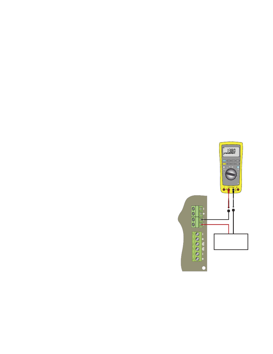
4-20 mA Test (4-20TEST)- The monitor contains a diagnostic routine that allows
the simulation of mA values between 4 and 20 to check output tracking. At the
4-20TEST prompt the arrow keys change the simulated mA output in increments
of 1 mA. The ammeter should track the simulated mA output. If a 4-20 mA test is
not necessary press MENU once to move to the next parameter.
Password (PASSWORD) - Password protection prevents unauthorized users from changing programming information. Initially
the password is set to all zeros. To change the password press ENTER once at the password prompt. The fi rst digit of the password
value will begin to fl ash. Using the arrow keys as previously described enter the password value. Pressing ENTER will store the
password and exit to run mode.
4-20
P
ulse
XMIT
RECV
+
-
10-30 VDC
POWER SUPPLY
10A MAX
FUSED
400mA
FUSED
CAT III
1000V
HOLD
MIN MAX
REL
Hz % ms
RANGE
AutoHOLD
FAST MIN MX
LOGGING
YES
CANCEL
SAVE
NO
SETUP
μA
mA
A
W
V
TEMPERATURE
COM
OFF
nS
W
VIEW MEM
CLEAR MEM
V
dB
mV
dB
ac+dc
V
ac+dc
A
mA
mV
ac+dc
mA
A
μA
ac+dc
μA
°C
°F
AC+DC
0
0
FIGURE 9 - 4-20 mA TEST SETUP