K factor calculation in standard cubic feet, Dynamic systems, Flow computer – Badger Meter QuikSert User Manual
Page 17: System pressure in psia (14 .73 + gage pressure) p, Standard pressure in psia t
K factor Calculation in Standard Cubic Feet
If the running conditions are held constant, the K factor adjustment for converting actual cubic feet to standard cubic feet will
also remain constant . In applications where a direct readout in standard cubic feet is desirable the following formula can be
used to determine the K factor for any given set of operating conditions:
Adjusted K factor =
P x T
Factory K factor x P x T
s
a
a
r
Example 2
A 2 inch B142 gas turbine meter has a factory K factor of 190 pulses per actual cubic foot and is installed in an application
operating at 100 psig at 80° F . Calculate the adjusted K factor that will allow the downstream electronics to display flow in
standard cubic feet .
Where:
Factory K factor = the K factor from the factory supplied in pulses per acf (actual ft
3
) .
P
a
= system pressure in psia (14 .73 + gage pressure)
P
s
= standard pressure in psia
T
a
= system temperature in °R (system temperature in ° F + 459 .67)
T
s
= standard temperature in °R (standard temperature in ° F + 459 .67) = 519 .76° R
Adjusted K factor =
190 x14.73 x (80 + 459.67)
(100 + 14.73) x (60 + 459.67)
=
190 x 14.73 x 539.67
114.73 x 519.67
=
1,510,375
59,622
= 25.333
OTEE:
N
If a Blancett readout such as the B3000 is being used, entering the operating pressure (Op Pres) and operating
temperature (Op Temp) will allow the readout to calculate the adjusted K factor automatically, eliminating the need
to do manual conversions .
In this example, as long as the pressure and temperature stay at 100 psig and 80° F, a K factor of 25 .33 will allow the
downstream electronics to display rate and total in scfm .
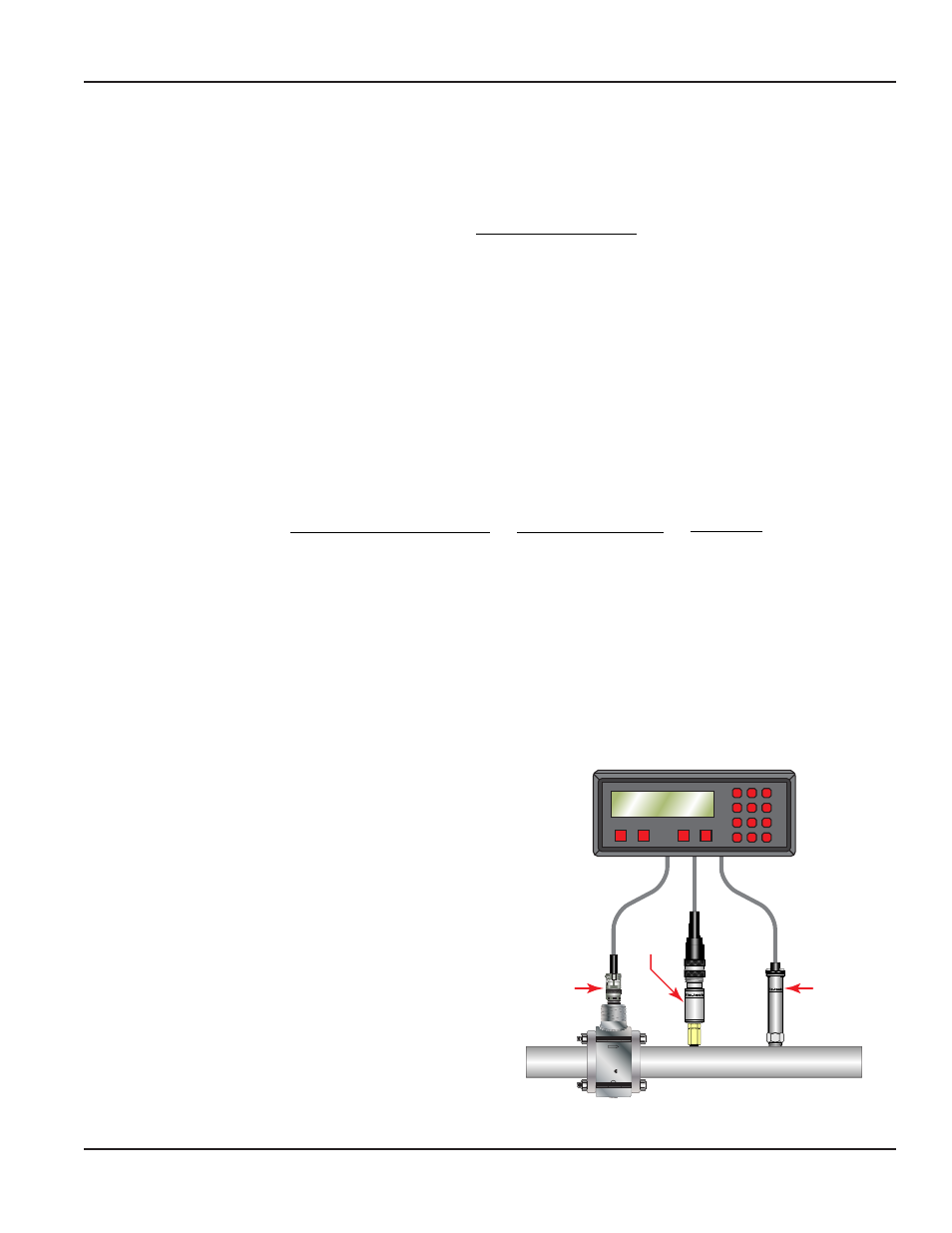
Dynamic Systems
In systems where pressure and/or temperature vary
constantly, the alternative to extracting scf from acf data is to
use of a flow computer and discrete pressure and temperature
transducers .
SENSOR S.N.: 64
PRESSURE SENSOR:
OUTPUT: 4 - 20 mA
HEDLAND
by
RT
D
HEDLAND
by
®
SENSOR S.N.: 64802
CAL. POINT: 154.9 °F: 12.
RANGE: -40 °F - 350 °F
OUTPUT: 4 - 20 mA
RACINE, WI USA
R
215035
ELECTRICAL SAFETY
E112860
Ci = 0µF Li = 1.65H
W/ B111113 INSTALLED
Vmax = 10V Imax = 3mA
S/N XXXXXXXX
2220 PSI
15.3 MPa
MODEL XXX-XXX
CL I DIV 1 GP C,D
SINGLE SEAL
350°F
MAX. WP/T
CL
ASSIFIED
®
C US
ADVANCE
BACKUP
CANCLE
DEC. PT.
1
2
4
4
5
6
7
8
9
ENT
0
CLR
A
B
C
D
Flow
Sensor
Pressure
Sensor
Temperature
Sensor
Flow Computer
Figure 10 Typical flow computer inputs
User Manual
Page 17
June 2014