Ecochill chiller, Water filter, Storage tank (only in versions a) – Airedale EcoChill 6kW - 46kW User Manual
Page 12: Desuperheater, Air vent, Expansion vessel, Cooling only (°), High pressure pressure switch (hp)
12
EcoChill
Chiller
Technical Manual 7300221 V1.1.0_02/2013
2.2.
HYDRAULIC CIRCUIT
Circulation pump (circulator)
P - N - A - Q versions.
Flow meter
Available in sizes "ECL 020 - 025 -
030 - 040 versions A with storage
tank".
Positioned upstream from evaporator,
it has the task of monitoring water flow.
On low flow the unit is disabled.
Differential pressure switch
Available in sizes:
"ECL 050 - 070 - 080 - 090 - 100 - 150 -
200 versions A with storage tank".
"ECL 020 - 025 - 030 - 040 - 050 - 070
- 080 - 090 - 100 - 150 - 200 standard
and P with pump"
Positioned between inlet and
outlet of evaporator. It has the task
of controlling that there is water
circulation, if this is not the case it
blocks the unit.
Water filter
This allows to block and eliminate any
impurities present in the hydraulic
circuits. It contains a filtering mesh
with holes that do not exceed one
millimetre.
It is indispensable in order to
prevent serious damage to the plate
exchanger.
Storage tank
(only in versions A)
It is required to reduce the number of
starts of the compressor and to even
the temperature of water to be sent to
the utilities.
- For ECL 020 - 025 25 l.
- For ECL 030 - 040 35 l.
- For ECL 050 - 070 - 080 - 090 75 l
- For ECL 100 - 250 - 200 100 l
Desuperheater
Plate type (AISI 316) desuperheater
, insulated externally with closed cell
material to reduce heat loss. ONLY
AVAILABLE FOR SIZES FROM 050
TO 200.
Air vent
(only for versions with hydronic unit or
with a pump)
− Manual type, discharges any air
pockets present. It has a shut off
valve to facilitate any replacement.
Expansion vessel
(only in versions complete with
storage tank or pump)
membrane type with nitrogen pre-
load.
Hydraulic circuit safety valve
(only in versions with hydronic unit or
pump).
Calibrated at 6 BAR and with
conveyable discharge, intervenes by
discharging the excess pressure in
the case of high system pressure
2.3. CONTROL AND SAFETY COM-
PONENTS
Low pressure pressure switch (LP)
Cooling Only (°)
With fixed calibration, placed on
low pressure side of cooling circuit,
inhibits functioning of compressor
if abnormal low suction pressure
occurs.
High pressure pressure switch
(HP)
− Cooling Only (°)
− Heat pump (H)
With fixed calibration, placed on
high pressure side of cooling circuit,
inhibits functioning of compressor if
abnormal work pressure occurs.
Low pressure transducer (TBP)
Heat pump (H)
Placed on low pressure side of
cooling circuit, it communicates the
suction pressure to the control board,
generating a pre-alarm if abnormal
pressure occurs.High pressure
transducer (TAP)
cooling only (D)
Heat pump (H) (HD)
Placed on high pressure side of
cooling circuit, it communicates the
discharge pressure to the control
board, generating a pre-alarm if
abnormal high pressure occurs.
ELECTRIC COMPONENTS
Electric Control Board
Contains the power section and the
management of controls and safety
devices. It is in compliance with
the IEC 60204-1 Standard and the
Directives regarding electromagnetic
version with
pump only
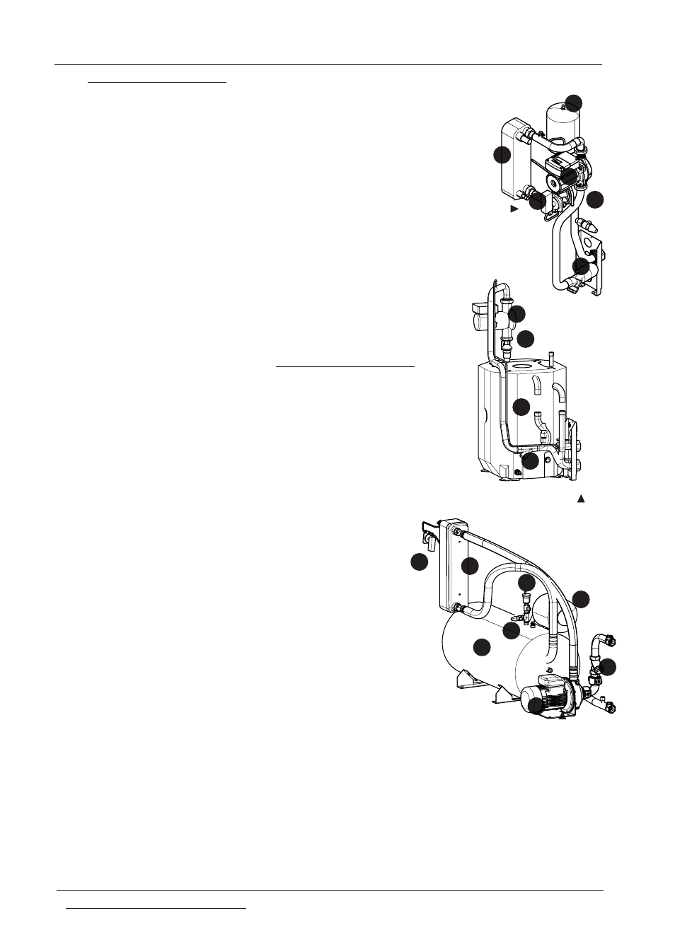
EXAMPLES OF HYDRAULIC CIRCUITS
the diagrams shown here are an example
version A ECL
020÷040 WITH
FLOODED
EVAPORATOR
KEY
1 Circulator/pump
2 Differential pressure switch/flow meter
(ECL 020÷040A)
3 Safety valve
4 Expansion vessel
5 Water filter
6 Plate heat exchanger
(inside the storage tank in ECL
020÷040A)
7 Vent valve
8 Storage
9 Electric resistance (ACCESSORY)
VERSION A 100 - 200
1
2
3
4
5
6
2
1
5
8
1
2
3
4
5
6
7
8