1general – West Control Solutions KS 800 Profibus Interface Manual User Manual
Page 5
General
5
9499 040 50511
1
General
The KS800 multi-temperature controller versions (9407-480-30001) are equipped with a PROFIBUS-DP
interface for transmission of process parameter and configuration data. Connection is via the 9-pole sub-D
connector socket. The serial communication interface permits connections to supervisory systems,
visualization tools, etc.
Another interface, which is always provided as standard, is the PC interface. This interface serves for
connecting an engineering tool, which runs on a PC.
Communication is according to the master/slave principle. KS800-DP is always slave.
Cable medium as well as physical and electrical interface proporties:
w
Network topologie
Linear bus with active bus termination at both ends. Stub lines are possible (dependent of cable type, a
maximum overall stub line length of 6,6m with 1,5Mbit/s and of 1,6m with 3-12Mbit/s is possible).
w
Transmission medium
screened, twisted 2-wire cable (Ä EN 50170 vol.2).
w
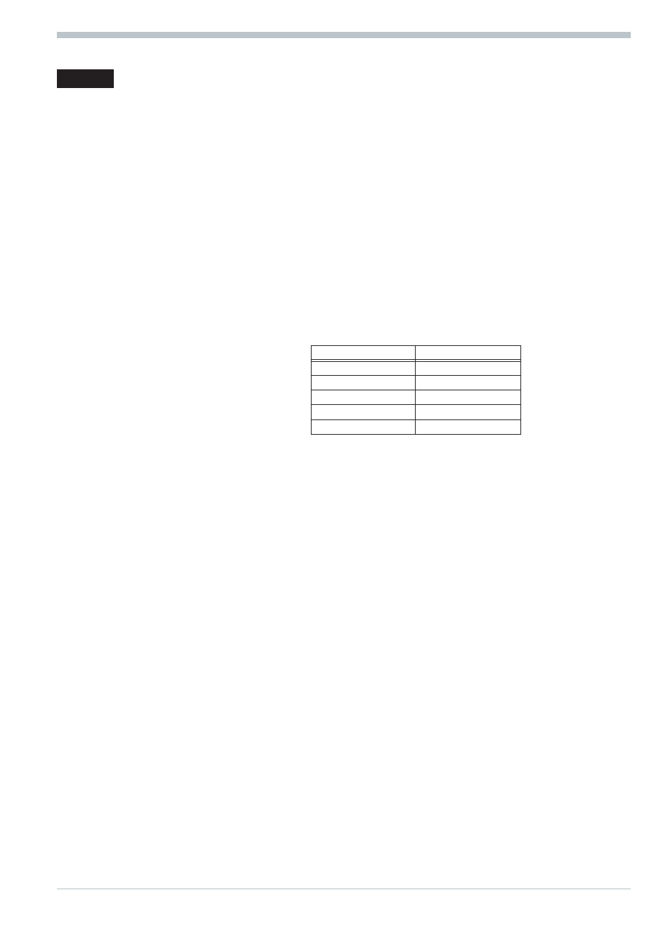
Baudrates and cable lengths (without repeater)
The maximum cable length is dependent of transmission rate.
The Baudrate is determined by the master configuration.
Automatic Baudrate
detection
Baudrate
Maximum cable length
9,6 / 19,2 / 93,75 kbit/s
1200 m
187,5 kbit/s
1000 m
500
kbit/s
400 m
1,5
Mbit/s
200 m
3 ... 12 Mbit/s
100m
w
Interface
RS485 connectable with sub-D connector (9-pole).
w
Address settings
Address setting is possible as follows:
- Adjustment via coding switches, range 00 ... 99, default 00
- adjustment via software, range 0 ... 126, default 126
With the coding switches set to ‘00’, the adjusted software address is valid.
A modified coding switch address is active only after switching on the supply voltage again.
w
32 instruments in one segment. Extension to 127 by means of a repeater is possible.
KS800 with PROFIBUS-DP interface offers many advantages with respect to handling and integration into a
PROFIBUS network.
w
Diagnosis and monitoring via COM-LED
LED off: error identification for ‘no bus access’ (so far not addressed by the master)
LED on: OK, cyclic data exchange running
LED blinks: (2Hz) Data exchange interrupted
LED blinks: (4Hz) PROFIBUS parameter setting and configuration error.
w
Particularities
Configurable process data modules
Direct input and output reading and writing
Output forcing
Easy connection to PLCs