Warning – Metex Shark Multi-Parameter Controllers & Analyzers User Manual
Page 13
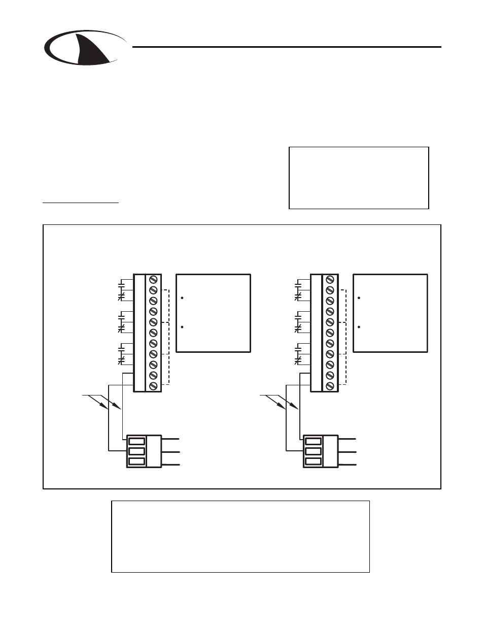
3.7 Relay connections
The Shark controller has three internal relays. Relays A and B are for control, the Alarm Relay
can be configured for alarm functions or as an additional control relay.
The connections to the relays are shown in the drawing.
Note that the AC power is internally connected to the
relay terminal plug P4. This is used to provide 120V or
240V AC power for the relay contacts.
Wire Specification: Size and fuse wire accroding to local
electrical code. Wire size not to exceed 14 AWG.
S
H
A
R
K
MULTI-PARAMETER CONTROLLER & ANALYZER USER’S MANUAL
Section 3 - Electrical Connections and Setup
Section 3 - Electrical Connections and Setup
Page 11
WARNING
DISCONNECT POWER FROM
CONTROLLER AND LOADS WHILE
CONNECTING TO THE RELAY
OUTPUT TERMINAL PLUG.
N.C.
N.O.
N.C.
N.O.
N.C.
N.0
GND
RELAY B
ALARM
RELAY A
NEUTRAL
GROUND
LINE
LINE OUT (21)
connections
Internal
NEUTRAL OUT (22)
RELAY CONNECTIONS FOR 120VAC
SHARK-120
P3
G
L
N
21
P4
22
23
24
25
26
27
28
29
30
31
W A R N I N G
PIN 21 must be
connected to relays
for power.
PIN 22 cannot be
connected to the
relays.
N.C.
N.O.
N.C.
N.O.
N.C.
N.0
GND
RELAY B
ALARM
RELAY A
RELAY CONNECTIONS FOR 240vac
SHARK-240
LINE
GROUND
LINE
LINE OUT (21)
connections
Internal
LINE OUT (22)
G
L
L
P3
21
P4
22
23
24
25
26
27
28
29
30
31
W A R N I N G
PIN 21 must be
connected to relays
for power.
PIN 22 cannot be
connected to the
relays.
Figure 3.6 Connections for Relay A, B and Alarm
Caution:
The contacts are rated at 10 amp N.O. and 5 amp N.C. Do
not exceed this rating. When switching larger currents, use an
auxillary relay switched by the controller relay to extend the
controller relay life. If the relays are controlling an inductive
load, use appropriate transient suppression at the load.
Dwg# N104-38