Metex Shark Multi-Parameter Controllers & Analyzers User Manual
Page 103
S
H
A
R
K
MULTI-PARAMETER CONTROLLER & ANALYZER USER’S MANUAL
Conductivity - Outputs Menu - 4-20mA CH1 Output 6.21
Conductivity - Outputs Menu - 4-20mA CH1 Output 6.21
Page 101
DOWN
DOWN
DOWN
DOWN
DOWN
UP
DOWN
DOWN
DOWN
DOWN
DOWN
DOWN
DOWN
DOWN
DOWN
UP
DOWN
UP
DOWN
DOWN
DOWN
UP
DOWN
DOWN
DOWN
UP
DOWN
DOWN
UP
DOWN
DOWN
UP
DOWN
DOWN
DOWN
Or press the
key to highlight the
Y character
Then press the key to store the
selection and return to the OUTPUTS
menu
Not stored
Stored
NOTE
PRESS THE AND KEYS
TOGETHER TO GO IMMEDIATELY BACK TO
RUN MODE
UP
DOWN
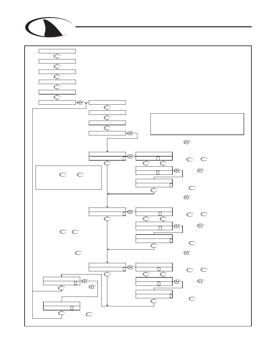
The TUNE fuction allows the user to
precisely adjust the 4-20 mA output to
compensate for any errors in the output
circuitry. Normally, find turning the 4-
20mA output is not necessary.
The make the adjustment, place an
accurate current meter in series with the
4-20 mA output, with the appropriate loads
connected. When the TUNE menu is
selected, the controller puts 20 mA out the
terminals. Use the or keys
to adjust the 20mA output to get exactly
20.
The TUNE value can be adjusted over the
range from 0 to 1000, these are unitless
RUN MODE
With "N" selected, pressing the
key will NOT store the selection, but
simply return to the OUTPUTS Menu.
This function is useful if you wish to
view the current selection without
making any changes.
The example below shows the 4-20 mA set to 4mA =400uS and 20mA =
1800uS. The output would then span 4 to 20 mA for a conductivity swing of 400
to 1800. Note that the span can reversed, in that 4 mA can be set to a high
conductivity value, and 20 mA can be set to a low conductivity value, effectively
reversing the control direction.
If you wish to change the setting, press the
key once which will move the cursor to the first
character of the value to be changed
Use the and
keys to change the setting
Press the key to accept the
setting and move to the next setting
Press the key once
which will move the cursor
back to the RH side of the
display.
The Controller has 2 4-20mA outputs, electrically isolated from
each other and ground. Either output can source current into a
maximum of 800 ohms. See Section 3.12 for wiring diagram.
Channel 1 (the primary output) is located on the flip out door,
terminal plug P6. Channel 1 is dedicated to track the process
and has fully independent and fully adjustable 4 & 20 mA
output adjustments. This will enable the operator to span the
output over the desired range.
STORE? Y N
STORE? Y N
4-20mA CH1 PROC
20mA TUNE 540 >
20mA TUNE 54 0 >
4-20mA CH1 PROC
4-20mA CH1 PROC
OUTPUTS
CALIBRATION
DIAGNOSTICS
UTILITIES
SETUP
1000uS 25.0C
4-20mA CH1
20mA TUNE 512 >
4-20mA CH1 PROC
4-20mA CH1 PROC
20mA OUT 2000 >
20mA TUNE 51 2 >
4-20mA CH1 PROC
4-20mA CH1 PROC
20mA OUT 180 0 >
20mA OUT 1800 >
20mA OUT 200 0 >
4-20mA CH1 PROC
4-20mA CH1 PROC
4-20mA CH1 PROC
4-20mA CH1 PROC
4mA OUT 0 >
4-20mA CH1 PROC
4-20mA CH1 PROC
4mA OUT 400 >
4mA OUT 40 0 >
4-20mA CH1 PROC
4mA OUT 0 >
ALARM RELAY
RELAY A
RELAY B