KROHNE IFC 110 Converter EN User Manual
Page 16
16
IFC 110 F
05/2003
2.3
Pulse outputs P and A1
2.3.1 Pulse output P for electronic totalizers (EC)
• Pulse output P is electrically isolated from all other circuits.
• Setting data and functions can note down in the Table in Sect. 3.
Please also refer to Section 2.7 ”Standard factory settings”.
• All operating data and functions are adjustable, see Sections 4.4 and 5.7, Fct. 1.05.
• Active mode:
uses the internal power supply, terminals E+/E-
Passive mode:
requires external power supply, U
ext
≤ 32V DC/24V AC, I ≤ 30mA
• Max. adjustable frequency 10 kHz
• Scaling
in pulses per unit time (e.g. 1000 pulses/s at Q
100%
flow) or
in pulses per unit volume (e.g. 100 pulses/m³ or US Gal).
• Pulse width
symmetric, pulse duty factor 1:1, independent of output frequency,
automatic, with optimum pulse width,
pulse duty factor approx. 1:1 at Q
100%
, or
pulse width range from 0.01 to 1 s adjustable as required for
correspondingly lower output frequency.
• Forward/reverse flow measurement (F/R mode) is possible, see Section 5.15.
• Connection diagrams see Section 2.6
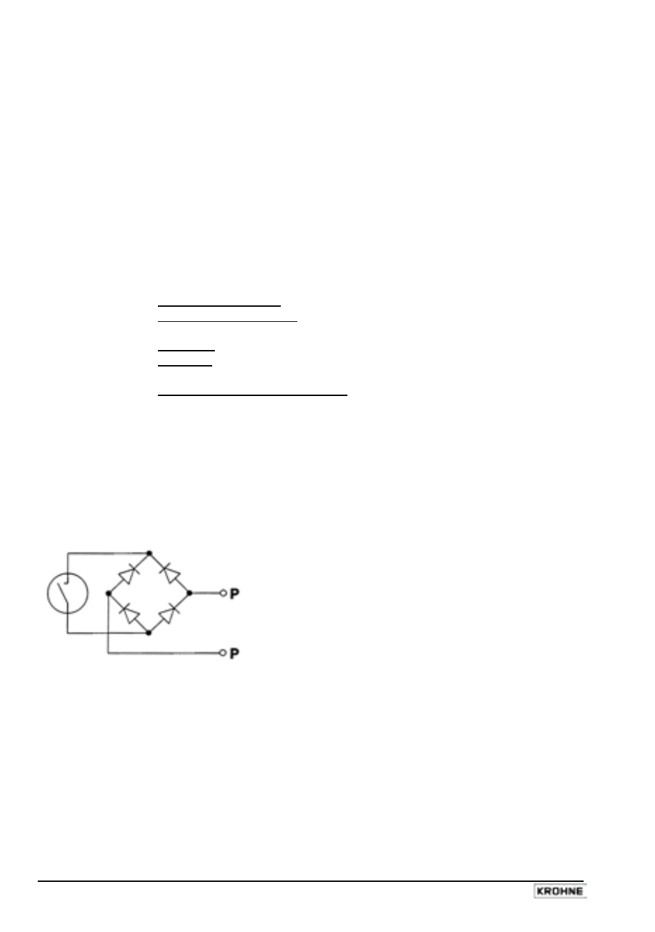
• Schematic wiring diagram for pulse output P for electronic totalizers EC
Similar to a relay contact, this pulse output switches direct and alternating voltages.