Technical data – KROHNE OPTITEMP TT 30 C-R EN User Manual
Page 35
TECHNICAL DATA
7
35
OPTITEMP TT 30 C/R
www.krohne.com
11/2012 - 4000753302 - MA OPTITEMP TT 30 C/R R02 en
7.1.2 Thermocouples
The thermocouple features two electric conductors made from different metals, connected at
one end. Each free end is connected to a compensation cable which is then connected to a
millivolt meter. This circuitry forms a "thermal circuit". The point at which the two electric
conductors connect is called the measuring point and the point at which the compensation
cables connect to the conductors of the millivolt meter is called the cold junction.
If the measuring point of this thermal circuit is heated up, a small electrical voltage (thermal
voltage) can be measured. If, however, the measuring point and the cold junction are at the same
temperature, no thermoelectric voltage is generated. The degree of thermoelectric voltage, also
known as electromotive force (EMF), depends on the thermocouple material and the extent of
the temperature difference between the measuring point and the cold junction. It can be
measured using the millivolt meter with no auxiliary power.
Simply put, the thermocouple behaves like a battery, the voltage of which also increases as the
temperature rises.
INFORMATION!
The characteristic curves and tolerances of commercially available thermocouples are
standardised in IEC 60584.
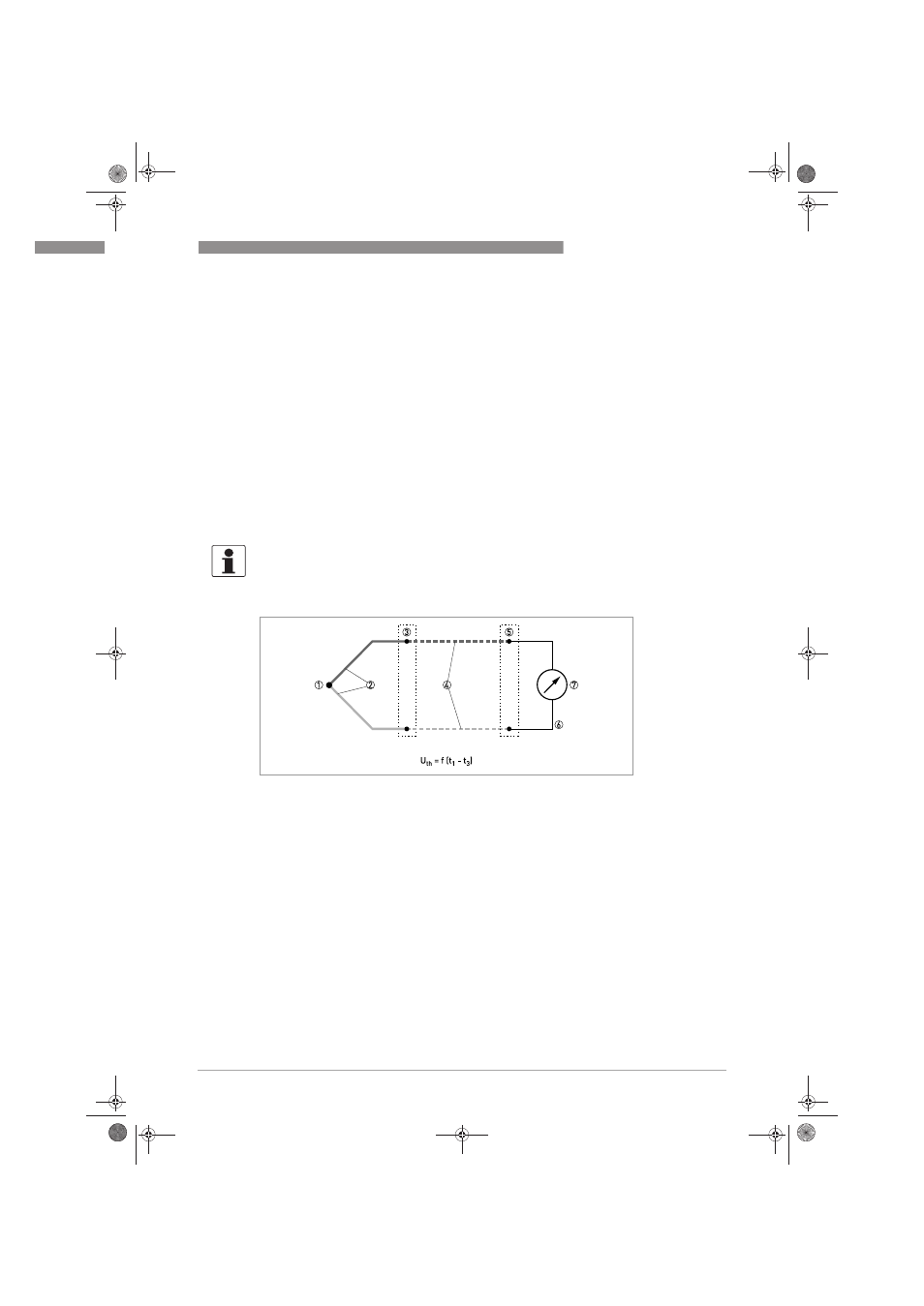
Figure 7-2: Thermocouple measuring circuit, schematic.
1 Measuring point t
1
(hot junction)
2 Thermocouple
3 Transition junction t
2
4 Compensation cable / extension cable
5 Reference junction t
3
(cold junction)
6 Copper conductor
7 Voltage meter U
th
.book Page 35 Friday, November 9, 2012 3:50 PM