Electrical connections – KROHNE OPTITEMP TT 30 C-R EN User Manual
Page 23
ELECTRICAL CONNECTIONS
4
23
OPTITEMP TT 30 C/R
www.krohne.com
11/2012 - 4000753302 - MA OPTITEMP TT 30 C/R R02 en
4.3.2 In-head transmitter (Ex)
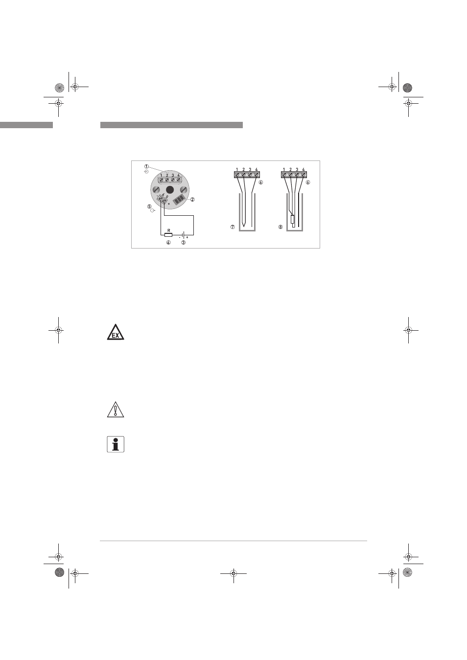
Figure 4-1: Connection diagram of the in-head transmitter (Non-Ex)
1 Input
2 Terminal for PC connection cable (contained in configuration set)
3 Power supply (6.5...36 VDC)
4 Load resistance
5 Output signal (4...20 mA)
6 SmartSense temperature sensor
7 Thermocouple
8 Pt100, 3-wire connection
DANGER!
The Ex transmitter can be installed in potentially explosive areas of zone 0, 1 and 2. It may only
be connected to Ex approved sensors or sensors that meet the requirements for "simple
equipment" in EN 60079-11:2007, section 5.7. During operations in potentially explosive areas
always note the relevant safety instructions and especially the following items:
•
The transmitter must be supplied by an intrinsically safe power supply unit or Zener barrier
placed outside of the potentially explosive area.
•
The output parameters of the Ex approved Zener barrier or voltage supply have to be less or
equal than the input parameters of the transmitter (i.e. U
i
, I
i
, P
i
, L
i
, C
i
).
CAUTION!
Note that the maximum output load always depends on the power supply. If the maximum output
load is exceeded, then the measured value will become incorrect. For further information refer
to the output load diagrams in the chapter "Technical data".
INFORMATION!
The transmitter has a polarity protection. Connecting the power supply with a wrong polarity will
not damage the transmitter.
.book Page 23 Friday, November 9, 2012 3:50 PM