Electrical connections – KROHNE OPTITEMP TT 10 C-R EN User Manual
Page 24
4
ELECTRICAL CONNECTIONS
24
OPTITEMP TT 10 C/R
www.krohne.com
02/2013 - 4000752703 - MA OPTITEMP TT 10 C/R R03 en
4.3.2 In-head transmitter (Ex)
DANGER!
The Ex transmitter can be installed in potentially explosive areas of zone 0. It may only be
connected to sensors that meet the requirements for "simple apparatus" in EN 60079-11:2007,
section 5.7. During operations in potentially explosive areas always note the relevant safety
instructions and especially the following items:
•
The transmitter must be electrically connected (terminal 4 and 5) via a certified isolating
interface/zener barrier having double or reinforced insulation which shall be placed outside
the hazardous area.
•
The output parameters of the Ex approved Zener barrier or voltage supply have to be less or
equal than the input parameters of the transmitter (i.e. U
i
, I
i
, P
i
, L
i
, C
i
).
CAUTION!
Note that the maximum output load always depends on the power supply. If the maximum output
load is exceeded, then the measured value will become incorrect. For further information refer
to the output load diagrams in the chapter "Technical data".
INFORMATION!
The transmitter has a polarity protection. Connecting the power supply with a wrong polarity will
not damage the transmitter.
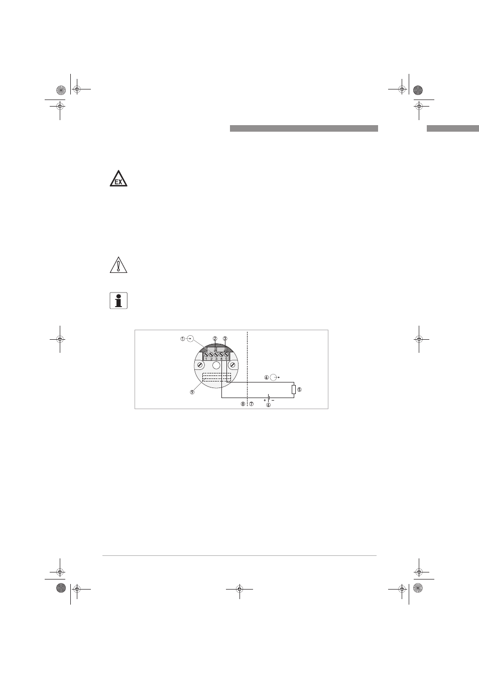
Figure 4-6: Connection diagram of the in-head transmitter (Ex)
1 Input signal (terminals 1, 2 and 3)
2 Potentiometer for zero point setting
3 Potentiometer for measuring span setting
4 Output signal, terminals 4 and 5 (4...20 mA)
5 Load resistance
6 Power supply
7 Safe area
8 Potentially explosive area
9 Solder pads
.book Page 24 Tuesday, February 26, 2013 1:43 PM