Figure 6. calibration screen – KEPCO KIT 219-0445, Cables for two High Power BOPs User Manual
Page 6
KEPCO, INC. " 131-38 SANFORD AVENUE " FLUSHING, NY. 11352 U.S.A. " TEL (718) 461-7000
FAX (718) 767-1102 " email: [email protected]
6
228-1472 REV 3
091903
b.
From the Settings menu, gain access to the Protected Settings menu by first entering the
password (see step 2c above).
c.
Press
@
from the Protected Settings menu to begin Calibration. The LCD shows
Calibration Multiple Units
Connect a short across Master Power Output.
Depress any Key to continue.
After connecting a short across output terminals of master, depress any key on the keypad.
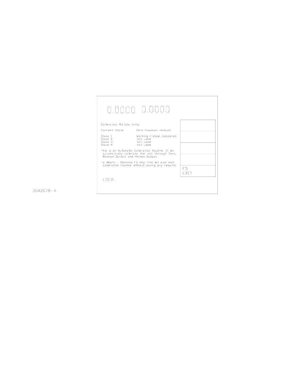
FIGURE 6. CALIBRATION SCREEN
d.
Press
#
from the main calibration menu to select Multiple. The Calibration Screen (Figure
6) is displayed. The status of the process is updated as calibration proceeds (this may take
approximately three minutes). The Current State is updated from zero to maximum and
minimum as the current calibration proceeds (voltage calibration is not required for the par-
allel pair).
e.
When the calibration is complete the LCD displays
PLEASE REMOVE SHORT FROM
OUTPUTS OF POWER SUPPLIES
Depress Any Key to continue.
After removing the short, depress any key on the keypad.
f.
When prompted, enter the calibration date (8 characters maximum, any format) using
U
or
ADJUST control to scroll through the characters and
T
or
R
to select the character posi-
tion, then press ENTER.
g.
Exit the Calibration menu by pressing
$
to save the settings upon power-up.
5.
Adjust the limits to reflect the increased current capacity of the parallel combination as follows:
VOLTAGE
SOURCE
VOLTAGE
CURRENT