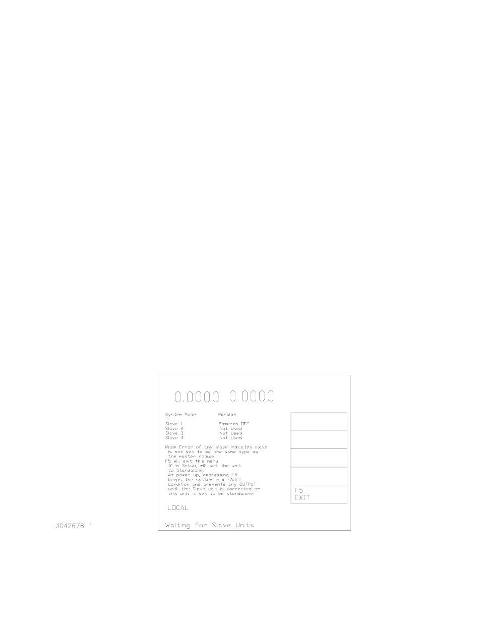
Figure 3. master power up screen – KEPCO KIT 219-0445, Cables for two High Power BOPs User Manual
Page 4
KEPCO, INC. " 131-38 SANFORD AVENUE " FLUSHING, NY. 11352 U.S.A. " TEL (718) 461-7000
FAX (718) 767-1102 " email: [email protected]
4
228-1472 REV 3
091903
3.
Turn on the unit to be configured as a master and note that upon power up the FAULT light will go
on (this is normal). Proceed as follows:
a.
From the main screen, press
%
to enter the Settings Menu.
b.
From the Settings menu, gain access to the Protected Settings menu by first entering the
password (see Step 2c above).
c.
From the Protected Settings menu, highlight
Unit Type
(use ADJUST control or
Y
or
U
keys) and press
!
to modify. Highlight
Master +1
and press
!
to apply the change.
d.
From the Protected Settings menu, under
Unit Type
highlight
Expansion
and press
!
to
modify. Highlight
Parallel
and press
!
to apply the change.
e.
Exit the Protected Settings menu by pressing
$
to test the system and to save the settings
for subsequent power-up cycles. The display shows the master power-up screen (see Fig-
ure 3).
NOTE: Pressing
%
to exit will cause the unit to revert to a standalone unit.
f.
The power-up master module screen (Figure 3) changes to show the status of Slave 1 (see
Table 2).
If the slave is recognized as ready, after about 10 seconds the master LCD reverts to the
Power On Default screen (see Figure 4). The slave also displays the Power On Default
screen (see Figure 5), except the unit will be in Current Mode, no function keys are active
and the Status message at the bottom is
KPAD Locked
, indicating the keypad is disabled.
The fault indicators on both units are off.
If the master power-up screen is still displayed after 10 seconds, the slave was not properly
recognized. Pressing
%
or turning power off, then on again, reconfigures the unit as a stan-
dalone unit. Verify that the BITBUS cable is installed correctly. Verify that the slave has
been properly configured as a slave per step 2 above. Repeat step 3. If the power up
screen still does not revert to the power on default screen, refer to troubleshooting.
FIGURE 3. MASTER POWER UP SCREEN
VOLTAGE
SOURCE
CPROTECT
VOLTAGE
CURRENT