13 programming circuit for driving the bop output, Voltage with a bipolar (±1v) signal -14 – KEPCO BOP-HV User Manual
Page 40
3-14
BOPHV112211
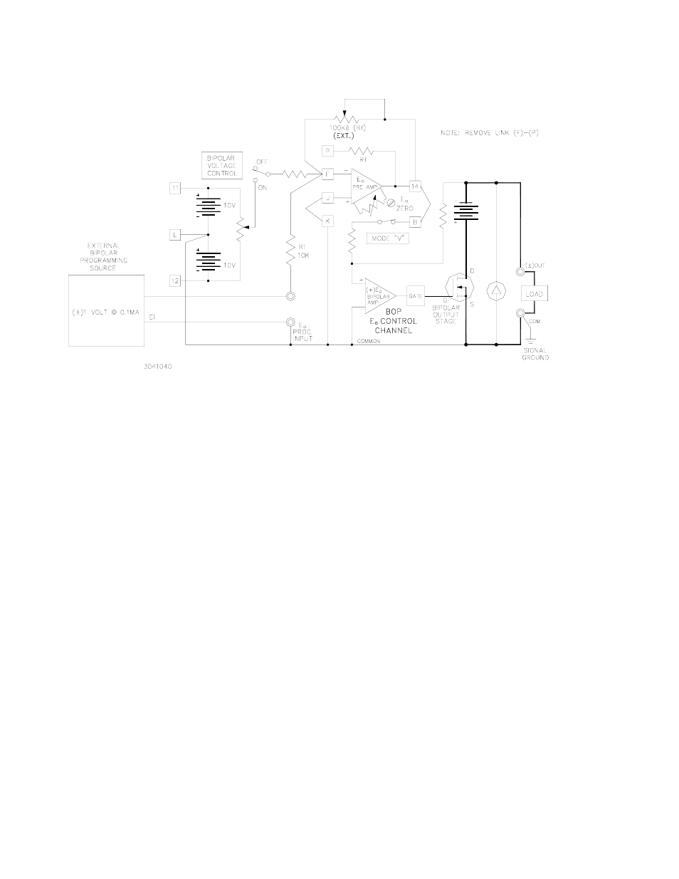
FIGURE 3-13. PROGRAMMING CIRCUIT FOR DRIVING THE BOP OUTPUT
VOLTAGE WITH A BIPOLAR (±1V) SIGNAL
The non-inverting input of the E
O
PRE-AMP is used for applications where the external pro-
gramming source has a high impedance and/or cannot supply the necessary 0.1mA drive cur-
rent, or where a negative going output swing is desired for a positive going input signal. The
necessary connections are illustrated in FIG. 3-14 for a E
O
PRE-AMP GAIN of unity (with the
built-in value for Ri retained and a short across Rf), although other gain configurations can be
chosen, according to the output equation for the non-inverting configuration:
where Rf is the external component between pins 14 and F, and Ri is the internal component
10K ohms, and the following conditions are present: the jumpers between pins P and F and
between pins J and K are removed, and a short-circuit is applied across the E
O
INPUT program-
ming terminals.
3.4
BOP OPERATION WITH REMOTE CONTROL OF THE CURRENT CONTROL CHANNEL
In the local (front panel) control mode, the BOP output current can be controlled by means of
the BIPOLAR CURRENT CONTROL, with the BIPOLAR CURRENT CONTROL SWITCH
closed, and the MODE SWITCH in the “CURRENT” position, over the full output range. The
control potential zero to (±)10V is applied to the I
O
PRE-AMP, operating with unity gain, to the
I
O
BIPOLAR AMP which drives the BIPOLAR OUTPUT STAGE with a fixed gain of 8mA per
volt (BOP 500M) and 4 mA per volt (BOP 1000M) respectively. A d-c control signal from zero
to(±)10 volts will, therefore, control the BOP output current through its specified range (refer
to FIG. 3-15).
E
O
PRE AMP
–
(
)
Ei
Rf Ri
+
Ri
------------------
=
/1