Bipolar amplifier (voltage mode) -13 – KEPCO BOP-HV User Manual
Page 39
BOPHV112211
3-13
tude, the basic programming circuit in FIG. 3-12 must be modified if the external signal source
cannot produce 10 volts and if the full BOP output voltage swing is required.
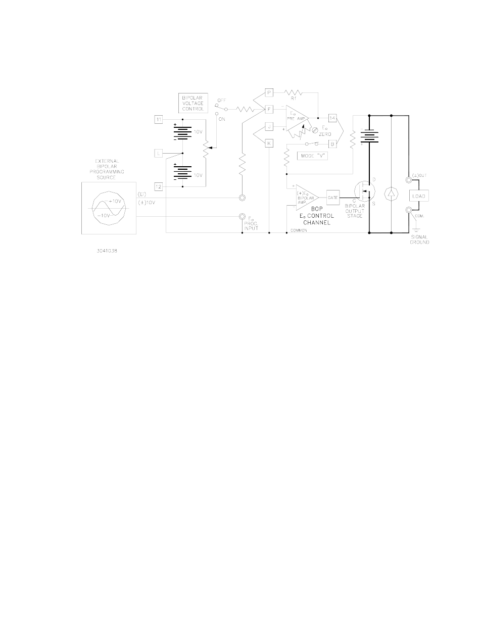
FIGURE 3-12. BASIC PROGRAMMING CIRCUIT FOR USE OF THE BOP AS A
BIPOLAR AMPLIFIER (VOLTAGE MODE)
If the EXT. PROGRAMMING SOURCE does not have sufficient amplitude to drive the BOP over
its full output range, the gain of the E
O
PRE-AMP must be changed from the built-in 1V per volt
value to suit the application. To calculate the required components for the new gain require-
ment, the output equation for the E
O
PRE-AMP in the inverting configuration is used:
where E
O
(PRE-AMP) = ±10V, and the values of Rf and Ri depend on the available amplitude of
the programming source. If, for example, a ±1 volt source is available, the ratio Rf/Ri must be
10, and the two resistor values can be Ri = 10K and Rf = 100K ohms, respectively. The built-in
resistor (Ri = 10K) can be retained, and only Rf must be replaced with a 100K metal film (1/2
watt) component. The necessary connections are illustrated in FIG. 3-13. Gain control (0 to 10)
can be exercised by making Rf a rheostat instead of a fixed resistor.
EO (PRE-AMP) = - Ei (Rf/Ri)