Between the bop and the load -5 – KEPCO BOP-HV User Manual
Page 31
BOPHV112211
3-5
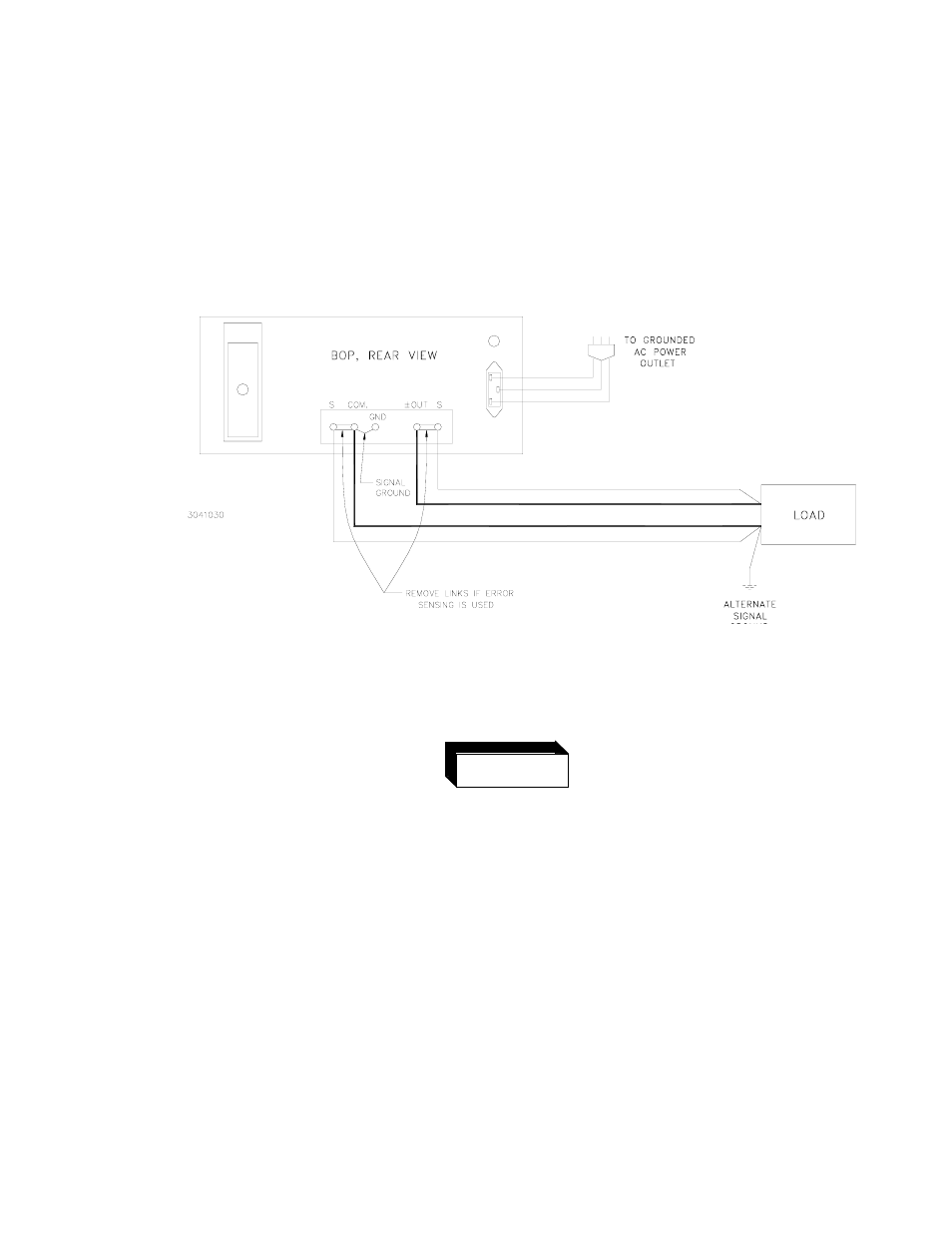
C) LOAD CONNECTION (II). The recommended load connection for all applications requiring
minimum load effect across a remote load is shown in FIG. 3-6. A twisted, shielded pair of
wires (AWG No. 20 minimum) is connected from the BOP sensing terminals to the load.
This “remote error sensing” technique will compensate for load wire voltage drops up to 0.5
volts per wire.
NOTE: OBSERVE POLARITIES:THE COMMON SENSING WIRES MUST GO TO THE
COMMON LOAD WIRE. THE (±) OUTPUT SENSING WIRE MUST GO TO THE (±)
OUTPUT LOAD WIRE.
FIGURE 3-6. LOAD CONNECTION WITH ERROR SENSING AND GROUNDING CONNECTIONS
BETWEEN THE BOP AND THE LOAD
E)
DC (SIGNAL) GROUND. (Refer to FIG.'s 3-5, 3-6). Specified ripple and noise figures for
operational power supplies are valid only with the common side of the output/load circuit
returned to a common ground point (refer to Section 1, Table 1-2). The common side of the
BOP output is shown grounded in FIG's 3-5 and 3-6, since it is “common” to both internal
reference source and any external signal source. If the application requires, the “common”
side of the BOP may be floated up to 500V d-c off ground. In this case, however, the com-
mon mode current (specified in Section 1, PAR. 1.3E),
will flow through the impedance of
whatever circuit is placed between common and ground and will give rise to a common
mode voltage. The signal ground point in the BOP/load circuit must consist of a single point
WARNING
D) A-C SAFETY GROUND. (Refer to FIG's 3-5, 3-6). The dangerous voltages present in this
equipment make it imperative that the case be kept at ground potential at all times. It is suf-
ficient to use a 3-wire line cord with 3-prong safety plug (supplied with this equipment) in
combination with a properly grounded outlet. If an adapter for a non-grounded outlet is
used, however, the case must be grounded separately. A separate “GROUND terminal is
provided for this purpose on the rear of the BOP. (See Section 2, FIG. 2-2).