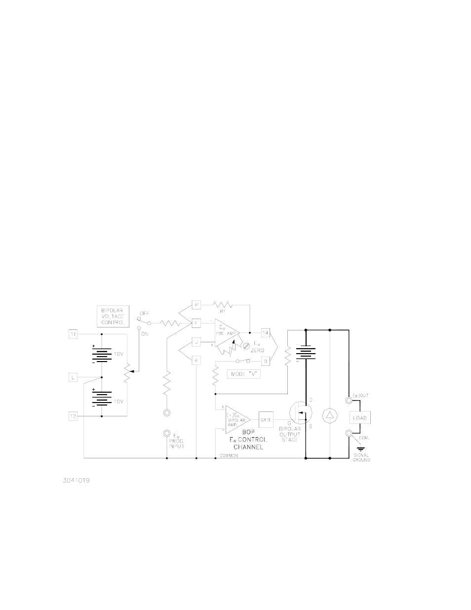
Figure 3-1. bop voltage control channel, Bop voltage control channel -2 – KEPCO BOP-HV User Manual
Page 28
3-2
BOPHV112211
A)
DIAGRAMS. Application and test set-up diagrams on the following pages show the sym-
bolic and simplified representation of the BOP circuitry in four (4) separate diagrams, as
indicated on FIGS. 3-1 through 3-4. The diagrams represent the four programmable cir-
cuits of the BOP.
1) Voltage Control Channel (FIG 3-1)
2) Current Control Channel (FIG 3-2)
3) (
±) E
O
Limit Circuits (FIG 3-3)
4) (
±) I
O
Limit Circuits (FIG 3-4)
The complete simplified diagram is represented at the beginning of Section 4 (see FIG.
4-1). THE FOUR CIRCUITS CAN BE PROGRAMMED SEPARATELY AS DESCRIBED
IN THE EXAMPLES IN THIS SECTION, OR THEY CAN BE USED SIMULTANEOUSLY
AS AN APPLICATION REQUIRES, WITH THE EXCEPTION OF THE TWO (2) MAIN
BIPOLAR VOLTAGE AND CURRENT CHANNELS WHICH ARE SELECTED BY THE
FRONT PANEL MODE SWITCH AND CANNOT BE OPERATED SIMULTANEOUSLY.
The numbered terminals in the diagrams correspond to the connector terminals on the
REAR PROGRAMMING CONNECTOR.
NOTE: BOP’s have front and rear output terminals. Only the front terminals are shown
on all subsequent simplified diagrams.
FIGURE 3-1. BOP VOLTAGE CONTROL CHANNEL