I — description, Table 1. bop 1kw-mg model parameters, Ii — unpacking – KEPCO BOP 1KW-MG Quick Start Guide User Manual
Page 2: Iii — equipment supplied, Table 2. equipment supplied, Description, Unpacking, Equipment supplied, See ta ble 2
2
228-1692 REV 3
112113
KEPCO, INC. " 131-38 SANFORD AVENUE " FLUSHING, NY. 11355 U.S.A. " TEL (718) 461-7000 " FAX (718) 767-1102
http://www.kepcopower.com " email: [email protected]
I — DESCRIPTION.
The BOP 1KW-MG Series hereafter referred to as
BOP, are true 4-quadrant programmable voltage and
current power supplies, meaning they are capable of
both sourcing and sinking power (see Figure 1).
These bipolar power supplies pass smoothly
through zero without switching to provide true ± volt-
age and ± current. These BOP power supplies use
switch mode technology for low dissipation. A bi-
directional, isolating, a-c input power factor correct-
ing (PFC) circuit recuperates energy sinked from an
active load and sends it back into the line to maintain
low dissipation.
These BOP power supplies are controlled digitally
from a menu-driven front-panel keypad or one of the
standard remote digital interfaces (GPIB or RS 232)
to set voltage and current and the four protection
limits (+voltage, –voltage, +current and –current.) A
front panel rotary adjuster allows real-time adjust-
ment of the output. A large LCD displays the mode
of operation, the settings, and the actual output volt-
age and current. Additionally, these BOP models
can be remotely controlled by an analog ±10V input
for the main channel (voltage or current), and a +1 to
+10V input for the limit channels.
BOP models are suitable for driving inductive loads
such as large magnets or motors, and for exercising
batteries. They are also suitable for characterizing
solar cell arrays, and powering many electrochemi-
cal reactions.
.
II — UNPACKING.
This instrument has been thoroughly inspected and
tested prior to packing and is ready for operation.
After careful unpacking, inspect for shipping damage
before attempting to operate. Perform the “Prelimi-
nary Operational Check.” on page 5. If any indication
of damage is found, file an immediate claim with the
responsible transport service.
III — EQUIPMENT SUPPLIED
.
See Table 2.
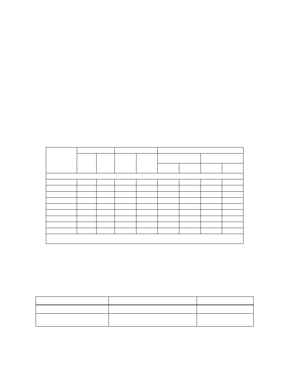
TABLE 1. BOP 1KW-MG MODEL PARAMETERS
Model
d-c Output Range
Closed Loop Gain
Output Impedance
Voltage
(V d-c)
Current
(A d-c)
Voltage
Channel
G
V
(V/V)
Current
Channel
G
I
(A/V)
Voltage Mode
(Series R - L)
Current Mode
(Parallel R - C)
R
d-c
(mOhms)
L
(
µ
H)
R
d-c
(Ohms)
C
(
µ
F)
1000 WATT MODELS
BOP 6-125MG
0 to ±6
0 to ±125
0.6
12.5
0.05
1.5
24
1150
BOP 10-100MG
0 to ±10
0 to ±100
1.0
10.0
0.1
2.0
50
1100
BOP 10-75MG
0 to ±10
0 to ±75
1.0
7.5
0.13
2.0
67
976
BOP 20-50MG
0 to ±20
0 to ±50
2.0
5.0
0.40
8.3
200
371
BOP 25-40MG
0 to ±25
0 to ±40
2.5
4.0
0.63
15.8
313
165
BOP 36-28MG
0 to ±36
0 to ±28
3.6
2.8
1.30
25
640
103
BOP 50-20MG
0 to ±50
0 to ±20
5.0
2.0
2.50
50
1250
55
BOP 72-14MG
0 to ±72
0 to ±14
7.2
1.4
5.14
104
2570
33
BOP 100-10MG
0 to ±100
0 to ±10
10.0
1.0
10.0
163
5000
16
NOTE: When connecting active loads, the steady-state voltage of the active load must not exceed the maximum voltage rating of the
BOP. Otherwise the overvoltage protection will shut down the power supply.
TABLE 2. EQUIPMENT SUPPLIED
ITEM
FUNCTION
PART NUMBER
Source Power Entry mating connector
Mates with source power entry connector
142-0381 (Kepco) (IEC 320)
PAR/SER CONTROL - IN
mating connector
Mates with PAR/SER CONTROL - IN port to allow
access to pins required for calibration
142-0488 (Kepco)