Software limits, Changing main channel software limit, Figure 6. max/min setting menu – KEPCO BOP 1KW-MG Quick Start Guide User Manual
Page 11
112113
228-1692 REV 3
11
KEPCO, INC. " 131-38 SANFORD AVENUE " FLUSHING, NY. 11355 U.S.A. " TEL (718) 461-7000 " FAX (718) 767-1102
http://www.kepcopower.com " email: [email protected]
activation press the CLEAR key to set the
value to zero and start over. When the desired
value is displayed, press ENTER. This causes
the new value to appear at the output and be
applied to the load if the output is enabled.
6. To program the corresponding Protect channel,
press
Y
or
U
as necessary to highlight the Pro-
tect channel. Then set the value using either of
the two methods described above. If the Protect
Entry setting is set to Independent, separate
entries for the positive and negative protect chan-
nel are possible. Otherwise the value entered is
applied to both positive and negative protect
channels.
NOTE: The BOP can be configured to show
the protection limits as either a single
value that applies to both protection
channels or show individual settings
for positive and negative protection
limits. See Operator’s Manual for
details
SOFTWARE LIMITS. Software limits prevent
programming of the main channel or the Protect
channel beyond the software limit value. Refer to
Operator’s Manual for a full explanation of software
limits.
Changing Main Channel Software limit.
This procedure allows the user to determine the
maximum value of voltage or current that can be
programmed.
1. Press
%
from the power-up screen to enter the
General Setup menu, then highlight Max/Min Set-
tings.
2. Press
!
to enter the Max/Min Settings submenu
(Figure 6). (If a Password is required, see Opera-
tor’s Manual for instructions.)
3. Highlight the voltage or current max/min value
and press
!
to change it. Software limits are
absolute values (do not use minus sign for nega-
tive limits). Use number keys to change the set-
ting, then
$
to save.
4. When complete, press
$
to save for power-up,
#
to abort, or
%
to apply the changes (without
saving for power-up) and exit.
5. Upon return to the power-up screen, the main
channel (voltage or current) is compared against
the main channel limits in effect. If the main chan-
nel exceeds the limit, it is set to zero.
6. Highlight the ±CPROTECT or ±VPROTECT max/
min value and press
!
to change it. Software
limits are absolute values (do not use minus sign
for negative limits). Use number keys to change
the setting. Press
$
to save, or
%
to abort.
7. When complete, press
$
to save for power-up,
or
#
to abort, or
%
to apply the changes (with-
out saving for power-up) and exit.
Upon return to the power-up screen, the new protec-
tion limit (voltage or current) is compared against the
protection limits in effect. If the new protection limit
setting is below the existing setting for the protection
limit, the protection channel (voltage or current) is
set to zero.
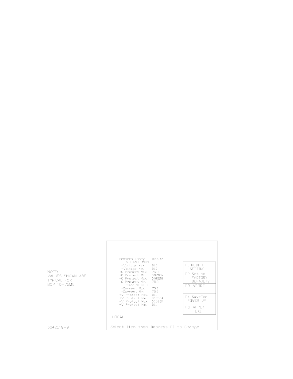
FIGURE 6. MAX/MIN SETTING MENU
VOLTAGE
SOURCE
VOLTAGE
CURRENT
0.0000 0.0000