GW Instek PSS-Series User Manual User Manual
Page 7
PSS-3203/2005 PROGRAMMABLE POWER SUPPLY
USER MANUAL
⎯ 8 ⎯
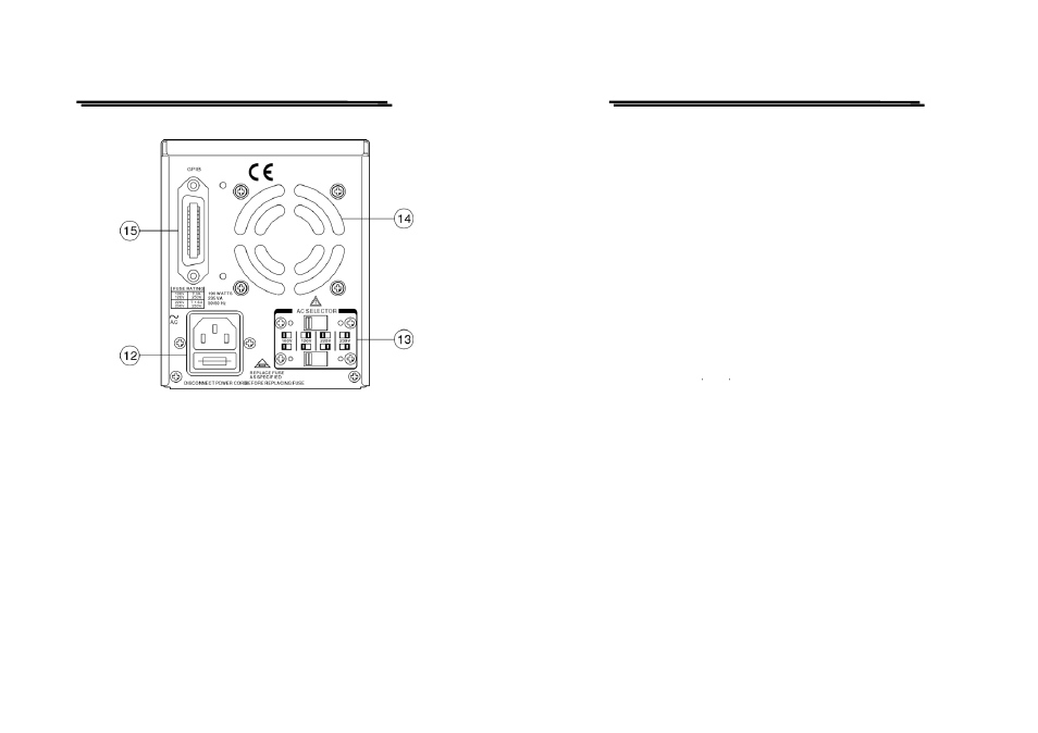
Figure 4-2 Rear Panel
PSS-3203/2005 PROGRAMMABLE POWER SUPPLY
USER MANUAL
⎯ 9 ⎯
1.
Power Switch
Connect the AC power, then press power switch.
2.
Display
Indicate the setting of voltage/current value, output
voltage/current value and the status of setting and
output.
3.
+Output Terminal
Positive output terminal.
4.
-Output Terminal
Negative output terminal.
5.
GND Terminal
Connect the ground terminal to chassis.
6.
Rotary Encoder
Wheel knob.
7.
V Set/I Set
(ENTER)
The key for switch over output voltage and output
current setting.
ENTER: The knob for value input or setting
confirmation.
8.
F/C
The knob for switching over coarse and fine
adjustment.
9.
MENU
The category of function setting (Output, OVP,
OCP, Contrast, Buzzer, Interface.)
PS. After switching to the picture of function
setting category, if there is no further setting action
within 4 to 5 seconds, the system will return to
previous setting picture or output display picture.
10.
LOCAL
Clear REMOTE control mode, and replace with
panel control.
PS. Get into calibration mode by pressing the knob
more than 5 seconds uninterruptedly,
11.
Output
Turn on or off output by pressing the knob.
12.
AC Power Socket
AC power input terminal.
13.
AC Select Switch
Switch Voltage to 100V, 120V, 220V or 230V,
50/60Hz.
14.
Cooling Fan
A cooling fan.
15
Interface
GPIB or RS-232C communication interface.