Ii - 3. jumper, Ii - 3, Ii - 4 – Fire-Lite IPDACT-2UD Technical Reference User Manual
Page 13: Led c ld4: alarm sending to the visoralarm
• LED C LD4: alarm sending to the VisorALARM.
ON: an alarm has been sent to the VisorALARM.
OFF: a response has been received to the sent alarm.
• LED D LD5: a bi-directional call to the alarm panel is in progress.
ON: there is a bi-directional call to the alarm panel. The LED located next to the
relays is off as the alarm panel has directly accessed the telephone line.
OFF: no bi-directional call in progress. The panel is operating normally.
II - 3. Jumper
The bridge labeled P1 operates by short-circuiting both pins through a metallic
element such as a screwdriver or a clip. This permits two tasks:
a)
On device startup this permits you to configure the IPDACT-UD with the
default configuration. For further information on how to activate the
default configuration, please see section IV.2.1.1.
b)
Access the telephonic console. This permits you to configure / monitor
the IPDACT-UD through a telephone connected to the said IPDACT-UD.
For further information, please see section IV.2.
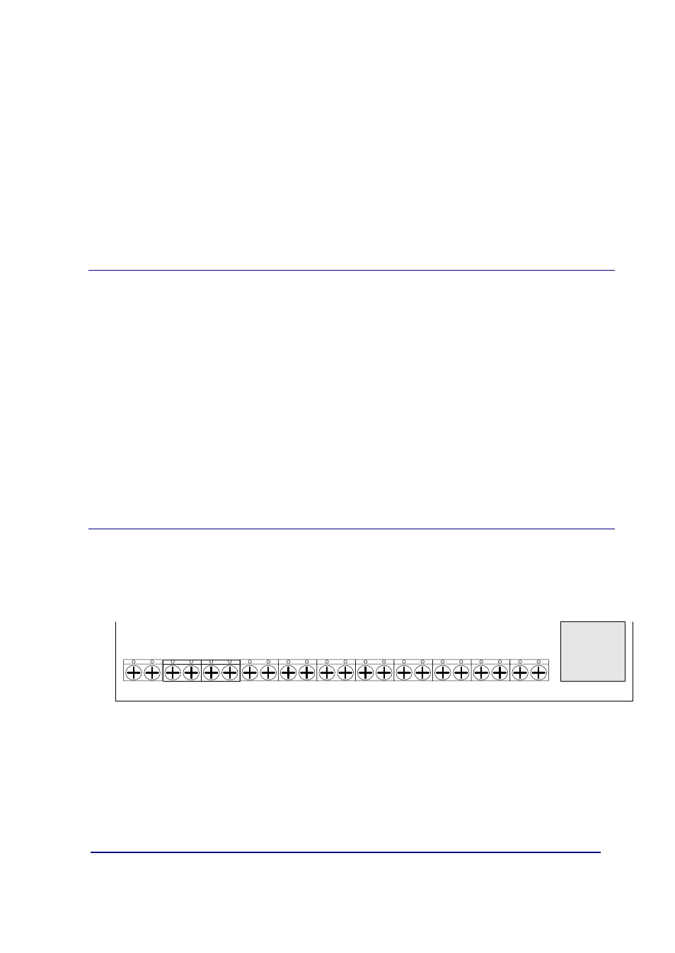
II - 4. Connection points to the Control Panel and
external
In order to connect the IPDACT-UD to the control panel and to power this,
there is a row of choc blocks. All the connections are limited in power. As
can be seen in the following figure, the connections are grouped in the
following manner:
FROM AP
PHONE
PSTN
NC C NO
OUT2
TAMPER
RJ45
ETHERNET
Female JACK
TO AP
NC C NO
OUT1
GND+12/24V
INPUT2
INPUT1
Figure 8. Connection choc block
Choc block connection to the control panel
• TO-AP: terminals proving telephonic connection to the control panel.
This must be connected to the control panel connection which this is
using to access the PSTN.
IPDACT-UD - Description
II-10
Doc.DM385-I
Rev. 2.0